
We are Open Source. Collaboration fuels Innovation.
Create, Innovate, and Share.
SECTION
A
1.1 Introduction 2
1.2 Table of Contents 3
1.3 Required Tools 4
1.4 Reseller Information 5
1.5 Components 6

A
1.1
Introduction
Welcome, and Thank you!
Thank you for your interest in the mapleMaker Mini V2 3D Printer.
The mapleMaker Mini introduces you to the world of additive
manufacturing and 3D printing. With your own 3D printer, your
concepts and design ideas can be translated from computer
drawings to physical objects in short period of time.
The goal of this guide is to introduce you to the parts and pieces that will be required before you can assemble your printer kit. Most of these items can be sourced both locally and from any number of online retailers.
The aim of this kit was to reduce costs and create an accessible,
hackable, upgradeable, and ultimately, user customizable
3D Printer. We believe that a 3D printer should evolve with it’s
users needs and knowledge, and become a platform for any
number of future upgrades and additions without the need for costly re-works or additional components.
Ultimately though, we want to empower the next generation of
designers, developers, and engineers by giving them the platform
and tools to suite their needs for today, tomorrow, and well into
the future.
We are Open Source. Collaboration fuels Innovation.
Create, Innovate, and Share.
Table of Contents
This guide is broken into several sections which encompasses the build process of the maplePrint Mini 3D printer. The process begins with the basic frame assembly and finishes with the final wiring and installation.
While we try to maintain the most up to date diagrams and illustrations, there may be slight differences between the illustrations contained within this guide, and the printed parts in your kit. If there are major changes or differences between the instructions
contained within and the printed parts, you should have received an updated insert in your kit containing the revised instructions.
Section A:
1.1 Introduction 2
1.2 Table of Contents 3
1.3 Required Tools 4
1.4 Reseller Information 5
1.5 Components 6
Section B:
2.1 Z Motor Assembly 16
2.2 Lower Frame Assembly 18
2.3 Upper Frame Assembly 24
2.4 Lower/Upper Frame Union 26
Section C:
3.1 Extruder Assembly 34
Section D:
4.1 X-Carriage Assembly 48
4.2 Y Carriage Assembly 62
4.3 Print Bed Assembly 76
4.4 Z Carriage Assembly 82
Section E:
5.1 GT2 Belt Installation 98
5.2 LCD Installation 102
5.3 RAMPS Installation 106
5.4 Upper Bed Installation 116
5.5 Wiring & Final Configuration 118
Section F:
6.1 Appendix 136
A
1.2
A
1.3
Before we begin the assembly process, it is vital that we have the proper tools to complete the build. Thankfully though, there are only a few tools required for the build. These tools were either included with your kit, or available at any local hardware or tool store. It is advised that you have a basic
understanding on how to properly use the tools required.
You will need the following:
#2.5 Allen Key (for use with M3 screws)
#3 Allen Key (for use with M4 screws)
#4 Allen Key (for use with M5 screws)
Ceramic screw driver (for adjusting RAMPS drivers)
Spatula (to remove printed parts from the print bed)
Exacto Knife (for trimming and cleaning parts)
Needle nose or similar pliars
Solder iron and solder
Nylon wire ties or zip ties (for securing wiring looms)
3M Blue painters tape (for printing with PLA)
Hot glue gun (to secure endstops)
Additional information regarding this build guide:
We’ve attempted to keep this build guide simple and easy to understand. We’ve broken the
assembly into several sections, and each step into individual illustrations to simplify the build
process further. Each illustrated step in this guide is also accompanied by a list of parts and
hardware required to complete the step. The illustrations of fasteners in these lists are printed to scale and may be used to size the hardware included in your kit. Simply place a fastener on top
of or next to the illustration to determine if its the correct one for the job!
Required Tools
Reseller Information
Below is a list of resellers and manufacturers of the components used in the mapleMaker Mini 3D Printer.
Some components may be sourced from your local home improvement retailers or
specialist hobby stores.
Electronics, motors & extruders
Folger Technologies, LLC: www.folgertech.com
Active Surplus: www.active123.com
EckerTech Inc: www.eckertech.com
Misumi www.us.misumi-ec.com/
Mixshop www.mixshop.com
Filastruder www.filastruder.com
SDP/SI CA www.sdp-si.com/
Skyhunt www.skyhunt.net
ROBOTDIGG www.robotdigg.com
Voxel Factory www.voxelfactory.com
Linear rods & movement
Folger Technologies, LLC: www.folgertech.com
ROBOTDIGG www.robotdigg.com
EckerTech Inc: www.eckertech.com
Mixshop www.mixshop.com
Fasteners
HD Supply Canada: www.brafasco.com (minimums may apply)
Fastenal www.fastenal.com (minimums may apply)
Misc. electronics
Digikey: www.digikey.ca
McMaster-Carr www.mcmaster.com (minimums may apply)
A
1.4
A
1.5
The following list comprises the components required to build your printer. For the purposes of this build, we have used ROBOTDIGG (www.robotdigg.com) to source the majority of the components. ROBOTDIGG offers almost every component required, minus fasteners and threaded rod. The hot end has been sourced through e3D’s authorized distributor, Filastruder (www.filastruder.com)
NEMA 17 48oz Stepper Motor
Quantity: 3
URL: http://www.robotdigg.com/product/206/Nema17-48mm-Stepper-Motor
Unit Cost: $9.50
NEMA 17 34oz Stepper Motor
Quantity: 2
URL: http://www.robotdigg.com/product/28/NEMA14-34mm-0.8A-or-1.25A-stepper-motor
Unit Cost: $6.80
Flexible Coupling - 5mm to 5mm
Quantity: 2
URL: http://www.robotdigg.com/product/83/Flexible-Coupling-5mm-Shaft-to-5mm-Screw
Unit Cost: $1.80
20 Tooth GT2 Pulley
Quantity: 2
URL: http://www.robotdigg.com/product/166/2GT-20-Tooth-6.35mm-Bore-Pulley
Unit Cost: $1.85
Open Ended 6mm GT2 Belt (2 meters
Quantity: 1
URL: http://www.robotdigg.com/product/10/Open-Ended-6mm-Width-GT2-Belt
Unit Cost: $1.80
LMS8UU (Short) 8mm Linear Bearing
Quantity: 12
URL: http://www.robotdigg.com/product/13/LM8UU-Linear-Bearing
Unit Cost: $0.60
Components
623ZZ Ball Bearing
Quantity: 4
URL: http://www.robotdigg.com/product/62/623ZZ-Ball-Bearing
Unit Cost: $3.60
Poloululu 4988 Stepper Drivers
Quantity: 4
URL: http://www.robotdigg.com/product/120/A4988-stepper-driver
Unit Cost: $3.80
Endstop
Quantity: 3
URL: http://www.robotdigg.com/product/141/Endstop,-Snap-Action-Limit-Switch-SS-5GL
Unit Cost: $0.60
RAMPS 1.4 Controller
Quantity: 1
URL: http://www.robotdigg.com/product/121/Ramps-1.4-Board
Unit Cost: $12.80
Arduino Mega 2560
Quantity: 1
URL: http://www.robotdigg.com/product/123/Arduino-Mega-2560-R3
Unit Cost: $15.80
RAMPS LCD Display
Quantity: 1
URL: http://www.robotdigg.com/product/122/RAMPS-LCD2004-with-SD-Socket
Unit Cost: $12.80
30mm Cooling Fan
Quantity: 4
URL: http://www.robotdigg.com/product/197/12V-3CMHotend-Cooling-Fan
Unit Cost: $1.50
A
1.5
12V 5A Power Supply
Quantity: 1
URL: http://www.robotdigg.com/product/350/12V-5AAC/DC-Adapter-Power-Supply
Unit Cost: $5.00
NEMA 17 34oz Stepper Motor
Quantity: 2
URL: http://www.robotdigg.com/product/28/NEMA14-34mm-0.8A-or-1.25A-stepper-motor
Unit Cost: $6.80
Thermistor Cable (1m)
Quantity: 1
URL: http://www.robotdigg.com/product/188/2pin-1MLong-Thermistor-Cables-w/-Dupont-Connector
Unit Cost: $0.40
Endstop Cables (1m)
Quantity: 3
URL: http://www.robotdigg.com/product/189/3pin-1MLong-Endstop-Cables-w/-Dupont-Connector
Unit Cost: $0.60
e3D Lite6 All Metal Hot End
Quantity: 1
URL: http://www.filastruder.com/products/lite6
Unit Cost: $35.00
MK8 Extruder Drive Gear
Quantity: 1
URL: http://www.robotdigg.com/product/242/MK8-Filament-Drive-Gear
Unit Cost: $3.00
Compression Spring (for Extruder & bed)
Quantity: 5
URL: http://www.robotdigg.com/product/71/Compression-Spring-for-Heatbed-and-Extruder
Unit Cost: $2.00
Components
762mm length Linear Rods (Pack of 6)
Quantity: 1
URL: http://www.robotdigg.com/product/113/Rostock-Mini-492mm-Long-8mm-Diameter-Smooth-Rod-Pack
Unit Cost: $24.00
Allen Key Set
Quantity: 1
URL: http://www.robotdigg.com/product/128/1.5,-2,-2.5,-3,-4-size-allen-key-with-ball-head-in-pack
Unit Cost: $2.00
Nylon Cable Ties (100 pack)
Quantity: 1
URL: http://www.www.robotdigg.com/product/127/Nylon-Cable-Ties-2.5*100mm-100pcs-n-3.6*200mm-100pcs-Pack
Unit Cost: $1.80
Ceramic Screwdriver
Quantity: 1
URL: http://www.robotdigg.com/product/181/Ceramicscrewdriver-for-A4988-stepper-driver
Unit Cost: $1.20
4GB SD Card
Quantity: 1
URL: http://www.robotdigg.com/product/345/4GB-SDCard-for-3D-Printing
Unit Cost: $4.50
Fasteners & Threaded Rod:
You will also require the following fasteners and threaded rod to complete the build.
These items can be purchased from your local hardware retailer or online.
M3X10mm Socket Cap Screw x135
M3X20mm Socket Cap Screw x8
M3X16mm Socket Cap Screw x8
M4X10mm Socket Cap Screw x1
M4X16mm Socket Cap Screw x2
M5X12mm Socket Cap Screw x60
M4X40mm Socket Cap Screw x1
4mm - 0.7 Stainless Steel Threaded rod
4mm - 0.7 Flat nut x3
1
A
1.5
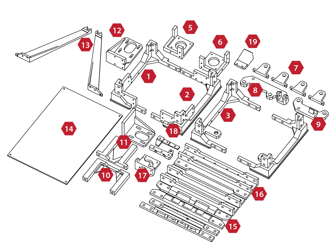
1. Left Lower Frame
2. Right Lower Frame
3. Right Upper Frame
4. Left Upper Frame
5. Left Z Motor Mount
6. Right Z Motor Mount
7. Z Axis Linear rod Mounts
8. Y Axis Carrier (Front)
9. Y Axis Carrier (Rear)
10. Y Axis Mount (Front)
14
13
Printed Components
10
12
11
17
1
18
2
11. Y Axis Mount (Rear)
12. Y Axis Motor Mount
13. Spool Holder Mounts (2)
14. Upper Bed (Printed)
15. Lower/Upper Frame rails (4)
16. Frame Upright Rails (4)
17. Extruder Mount
18. Extruder Idler Arm
19. Print Cooler Duct
5
6
3
15
19
8
16
4
7
9
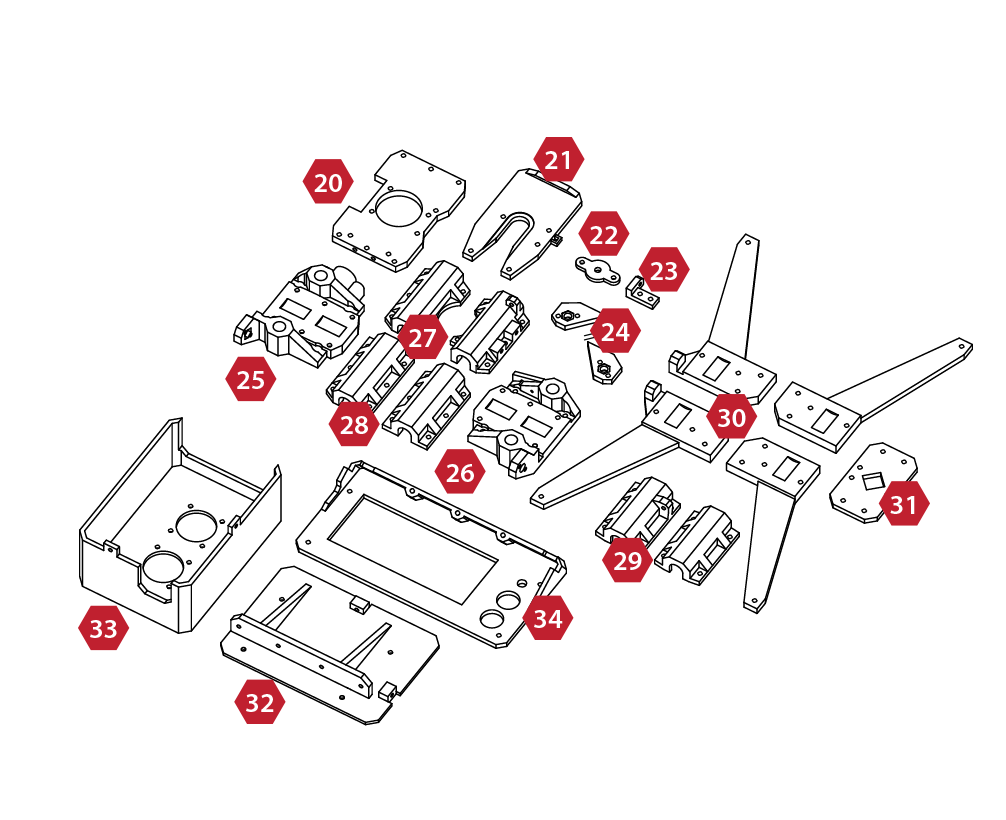
20. Extruder Base Mount
21. Hot-End Mount
22. X Axis Idler Cover
23. Z Axis Adjustment Mount
24. Z Axis Nut Covers
25. X Axis Assembly (Left)
26. X Axis Assembly (Right)
27. X (Extruder) Bearing Carriers (2)
33
25
32
20
28
27
26
34
21
28. Z Axis Bearing Carriers (2)
29. Y Axis Bearing Carriers (2)
30. Lower Bed Frame (4)
31. Lower Bed Union
32. Electronics Backplate
33. Electronics Enclosure
34. LCD Frame Assembly
22
24
29
23
30
A
1.5
31
2
SECTION
B
2.1 Z Motor Assembly 16
2.2 Lower Frame Assembly 18
2.3 Upper Frame Assembly 24
2.4 Lower/Upper Frame Union 26

1
2
B
2.1
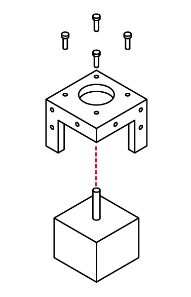
Z Motor Assembly (Right Front)
Locate the Hardware bag marked:
Z-Motor Mounts
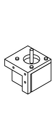
Locate the Right Front Motor mount, the
upright mounts should face the outside of the frame.
From the Stepper Motor package, select 1 of the 34mm (short) stepper motors.
From the Fastener package, select:
4 M3x10 cap screws
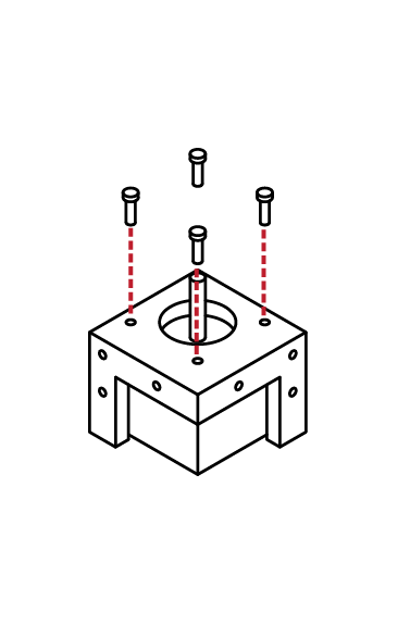
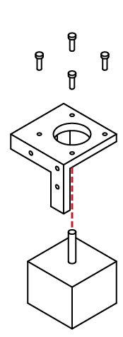
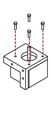
Insert the Stepper Motor into the base of the Right Front Motor Mount
The threads on the face of the Stepper Motor should align with the 4 holes of the Right Front Motor Mount.
X 4
N/A
M3 x 10
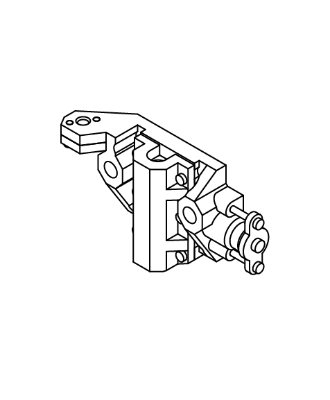
Z Motor Assembly (Right/Left Front)
Using the M3 Hex wrench, screw the
4 M3 x 10 cap screws through the Right Front Motor mount into the stepper motor.
Note: Take care not to over-tighten the screws, or you may break the motor mount.
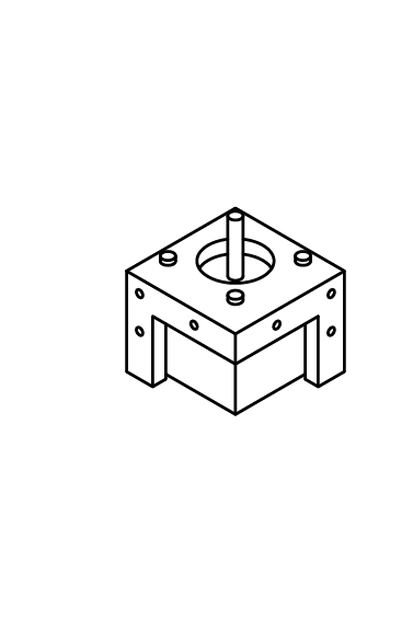
Congratulations, the Right Front Z Motor Assembly is complete!
N/A
Alert: Left Front Z Motor Assembly
Collect the Left Front Motor Mount, the
second 34mm (short) stepper motor and
4 M3x10 cap screws.
Repeat Steps 1-3 to complete the Left Front Z Motor Assembly
X 4
M3 x 10
B
2.1
3
!
1
2
B
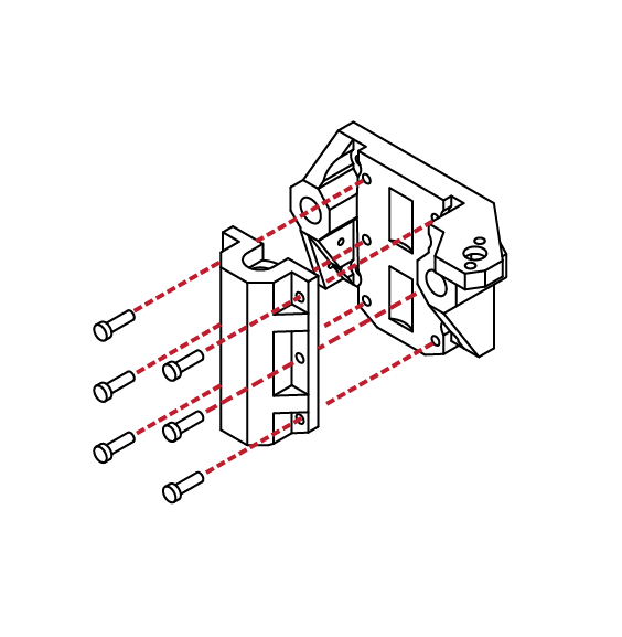
2.2
Lower Frame Assembly
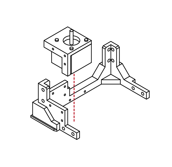
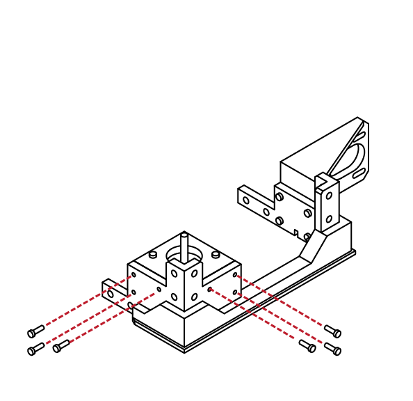
Locate the lower left side frame, and collect the left Z motor assembly completed in the previous steps.
Place the motor assembly into the lower left frame.
The screw holes on the motor assembly should match the screw holes in the lower left frame assembly.
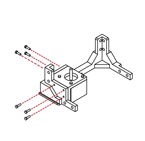
From the hardware bag, collect 6 M3 X 10 screws.
Using your M3 Hex wrench, attach the motor assembly to the lower frame assembly.
N/A
X 6
M3 x 10
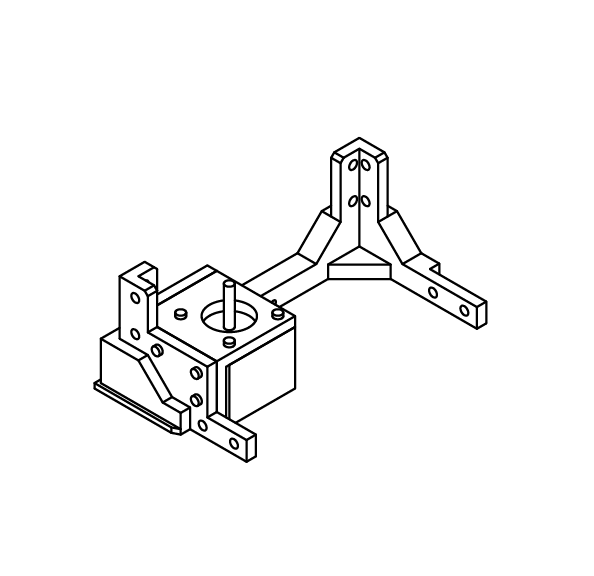
Congratulations, you’ve completed the left lower frame assembly.
Check the fit and ensure that all screws are tight.
Don’t over tighten the screws, as this may strip the parts.
N/A
Locate the Y axis motor mount from your printed parts kit. This mount is longer than the similar X axis motor mount.
Also from your printed parts, locate the
lower right side frame.
Check the fitment of both pieces before
proceeding to the next step.
N/A
B
2.2
3
4
5
6
B
2.2
Lower Frame Assembly
From the hardware bag, select 4 M3 X 10 screws.
Using the screws, attach the Y axis motor mount to the lower right side frame.
The Y axis motor mount is now complete.
Check the fitment of the mount to the lower frame.
Ensure that the mount is tight to the frame and secure.
Do not over-tighten the screws holding the mount in place.
X 4
N/A
M3 x 10
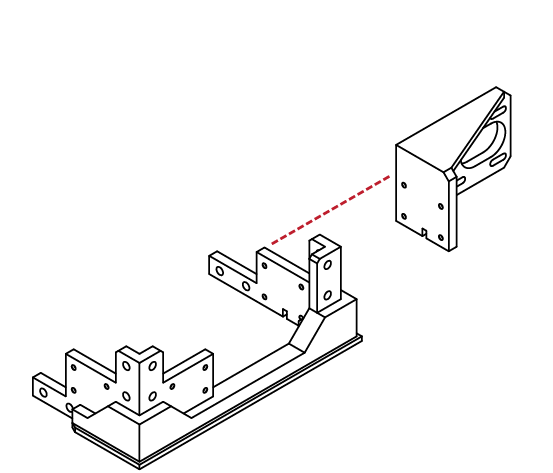
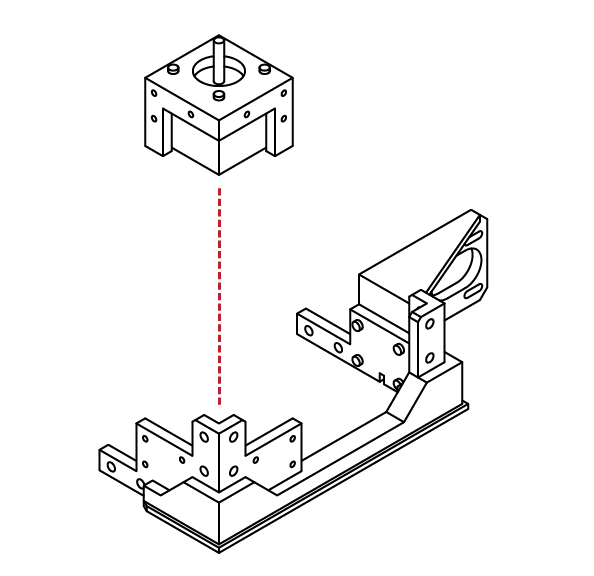
Locate the right Z motor assembly that was assembled in the previous steps.
Place the motor assembly into the lower right frame.
The screw holes on the motor assembly should match the screw holes in the lower right frame assembly.
N/A
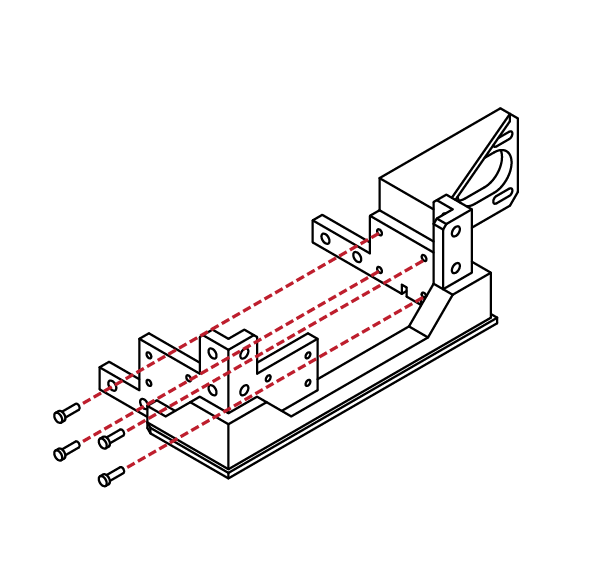
From the hardware bag, collect 6 M3 X 10 screws.
Using your M3 Hex wrench, attach the motor assembly to the lower frame assembly.
X 6
M3 x 10
B
2.2
7
8
1
2
B
2.2
Lower Frame Assembly
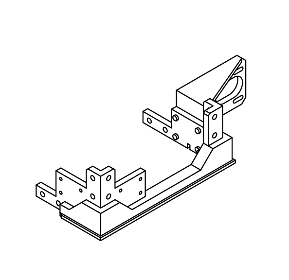
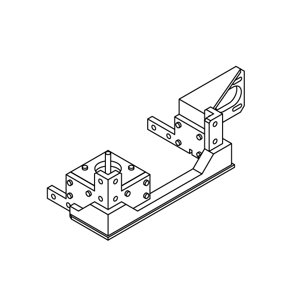
Congratulations, you’ve completed the right lower frame assembly.
Check the fit and ensure that all screws are tight.
Don’t over tighten the screws, as this may strip the parts.
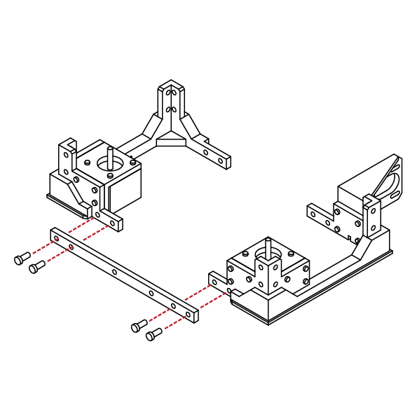
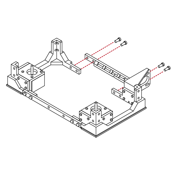
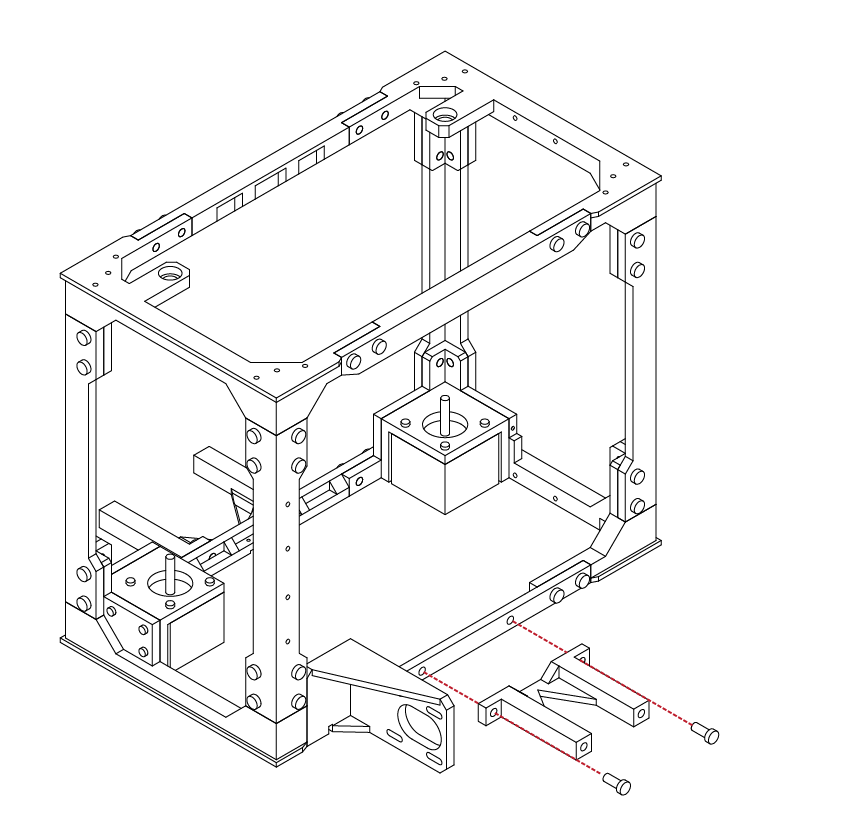
From the printed parts kit, locate the front lower frame rail. The front lower frame rail should be longer in length than the rear.
Take the left and right lower frame
assemblies and match it to the lower front frame rail.
From the hardware bag select 4 M5 X 12 screws and using your hex wrench screw them through the lower front rail and into the left and right lower frame assemblies.
Check to make sure the pieces align and there are no gaps.
N/A
X 4
M5 x 12
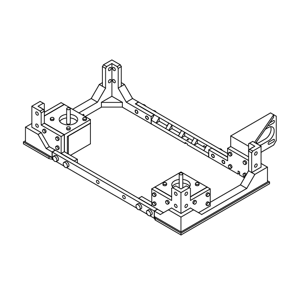
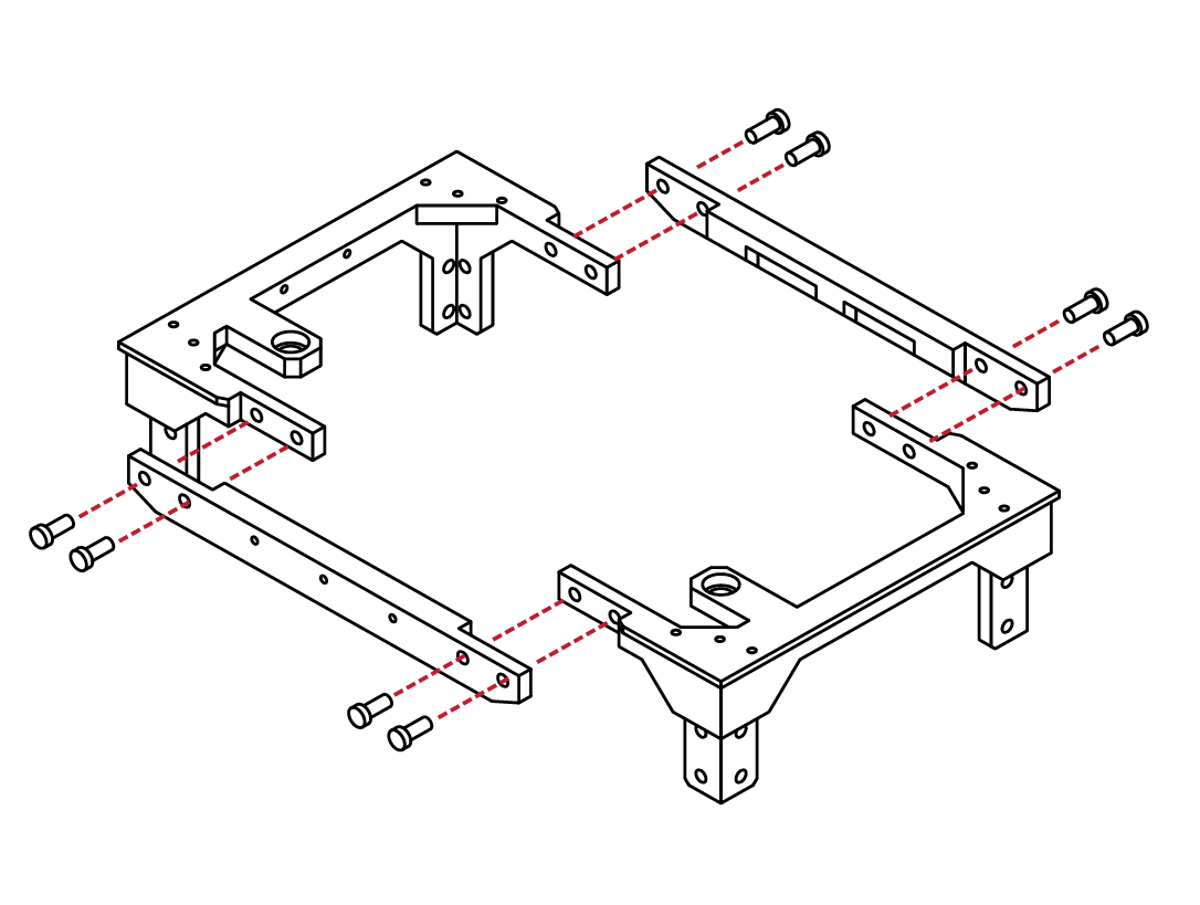
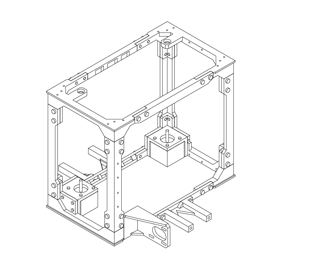
Similar to the previous step, select the
rear lower frame rail from the parts kit. This rail is longer than the front lower rail.
Select 4 M5 X 12 screws from the hardware bag.
Like the previous step, take the screws and using your hex wrench attach the rear frame rail to the lower frame assemblies.
Ensure that the screws are tight and that there are no gaps or alignment issues with the pieces.
X 4
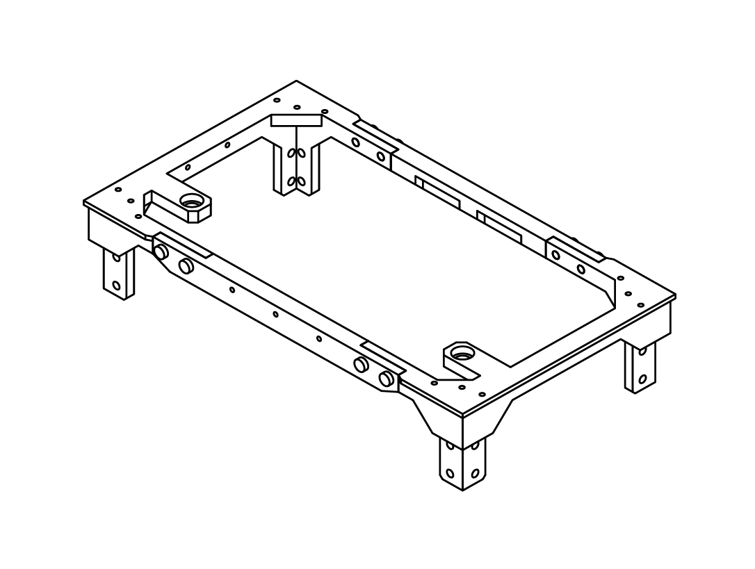
Congratulations! You’ve completed the
lower frame assembly!
Take a break and marvel at your
accomplishment.
N/A
M5 x 12
B
2.2
3
4
1
B
2.3
The upper frame assembly is similar to the lower frame assembly. You will need to locate the left and right upper frame assemblies, as well as the front and rear upper frame rails.
The front frame rail is easily identified by the 3 screw holes for the LCD panel. You will also need to collect
8 M5 X 12 screws from the hardware bag.
Like the lower assembly, use your hex wrench to secure the upper frame rails to the upper frame assemblies.
Upper Frame Assembly
X 8
M5 x 12
N/A
Congratulations! You’ve assembled the upper frame
assembly! Wasn’t that easy?
Take a moment to check that the frame appears square and that the frame rails are tight to the frame assemblies.
Ensure that the screws are not over-tightened as well.
B
2.3
2
1
B
2.4
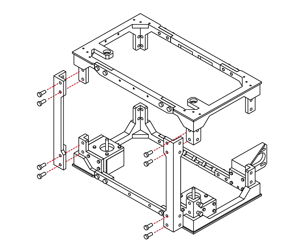
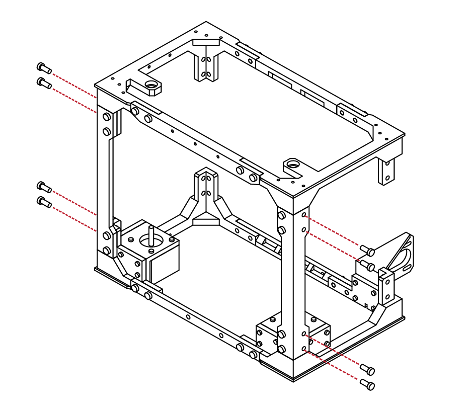
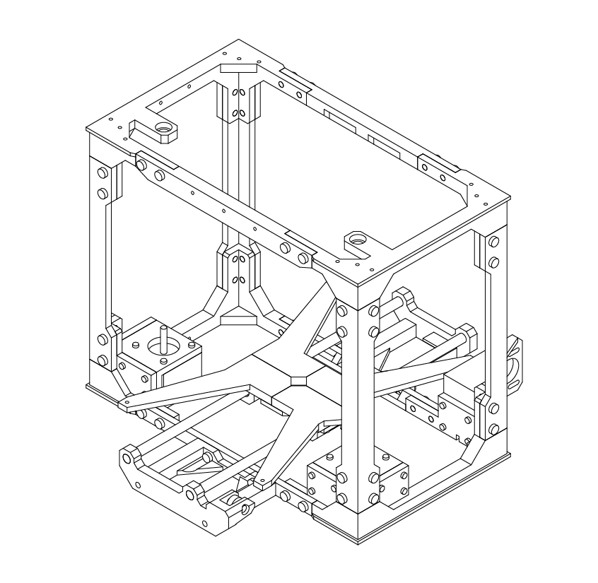
From the parts kit, select 2 of the main frame uprights. These pieces are universal and can be fitted in any position.
Select 8 M5 X 12 screws from your hardware bag as well.
Using your hex wrench, install the screws into the frame uprights, and then into the lower and upper frame assembly.
It is best to assemble the lower frame before the upper frame assembly.
Lower & Upper Frame Union
X 8
M5 x 12
X 8
M5 x 12
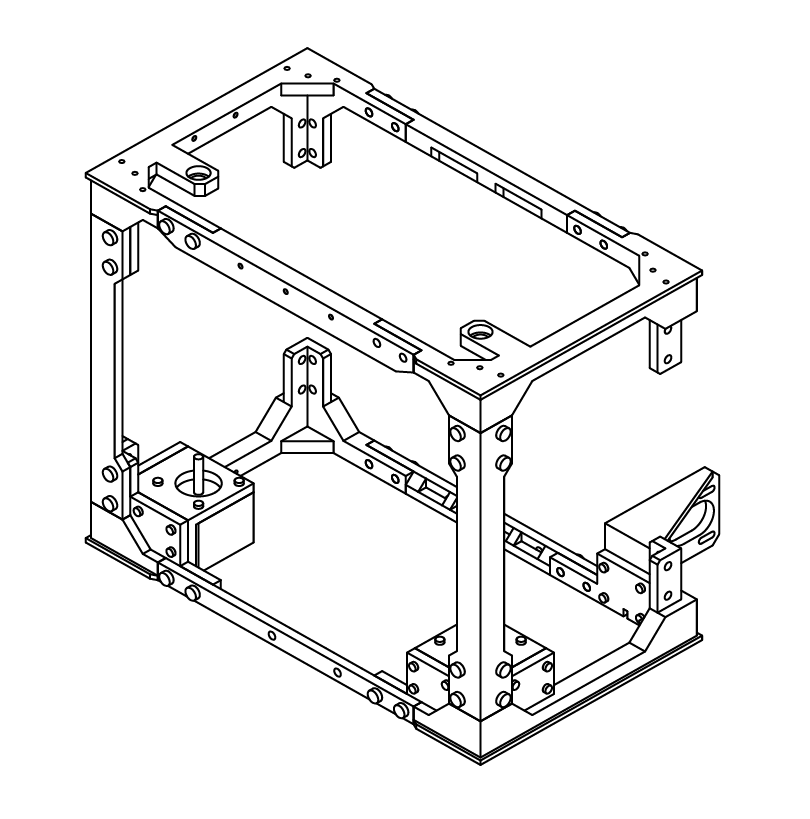
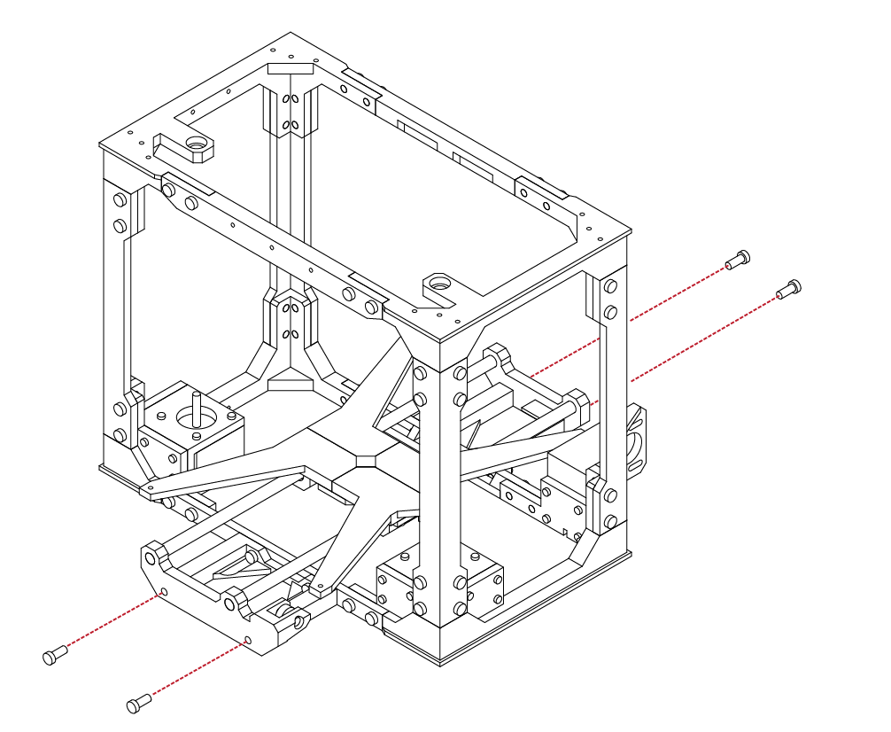
With the first uprights installed, from your hardware
bag, select 8 additional M5 X 12 screws.
Using your hex wrench, install the screws into the
uprights.
Ensure that the uprights are tight and aligned to the
upper and lower frame assemblies.
B
2.4
2
3
B
2.4
Congratulations! You’ve installed half of the frame!
We’re almost done!
Lower & Upper Frame Union
N/A
X 8
M5 x 12
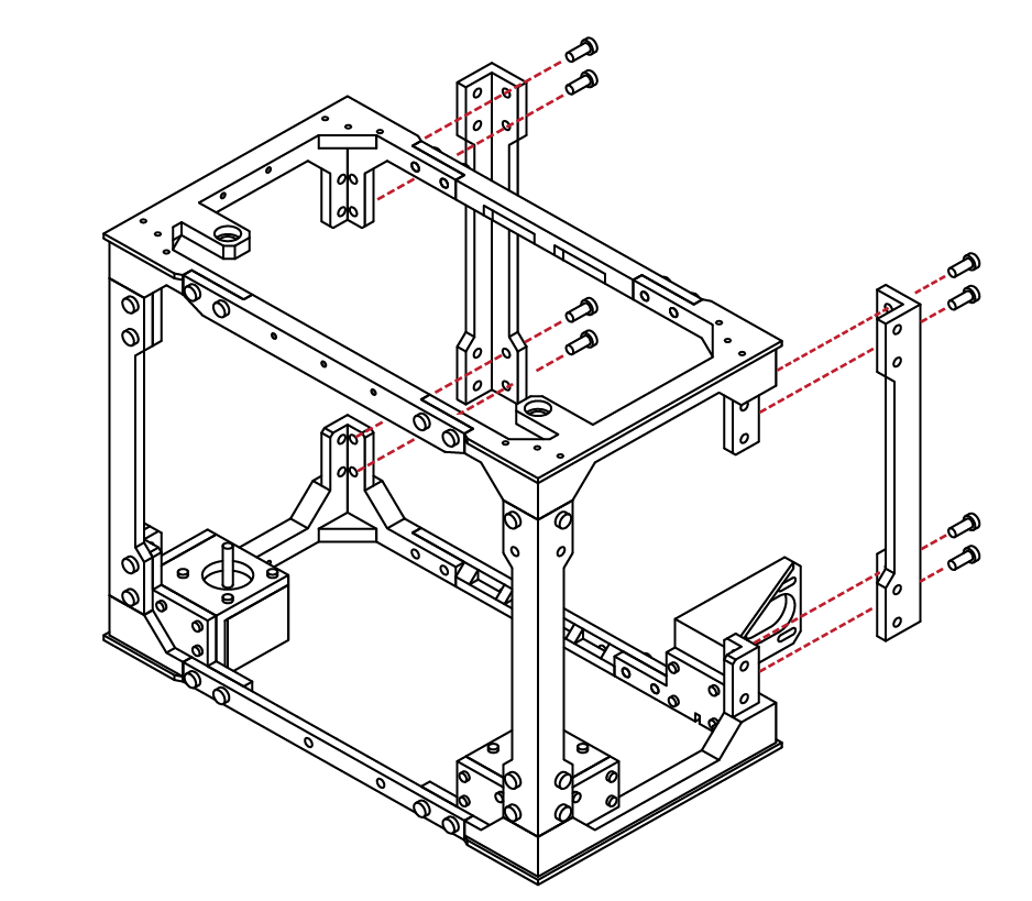
Like our previous step, select the two remaining frame uprights and check their fitment to the rest of the frame assembly.
Select 8 M5 X 12 screws from the hardware bag.
Using your hex wrench, attach the two uprights to the rear of the frame.
B
2.4
4
5
B
2.4
Select 8 additional M5 X12 screws from your
hardware bag.
Using your hex wrench, install the remaining screws into the uprights and frame assemblies.
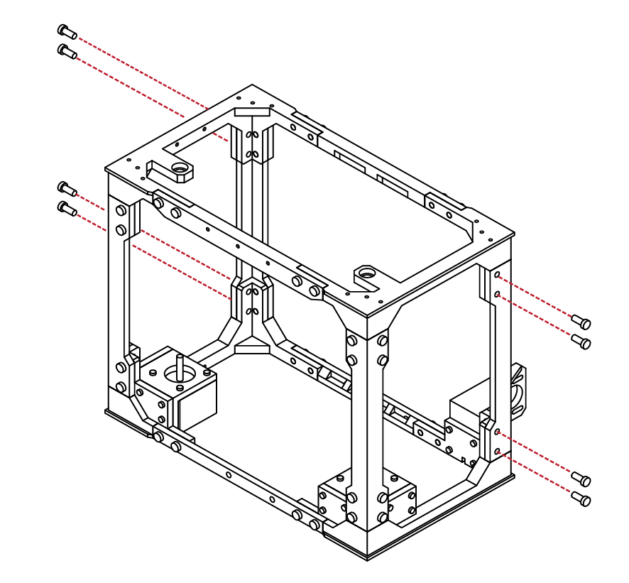
Lower & Upper Frame Union
X 8
M5 x 12
N/A
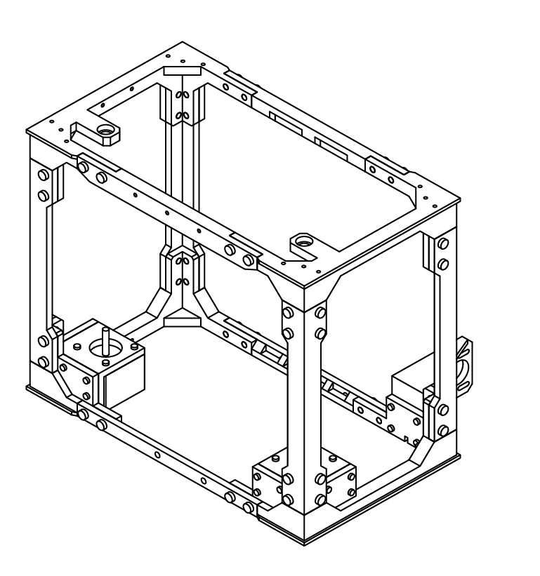
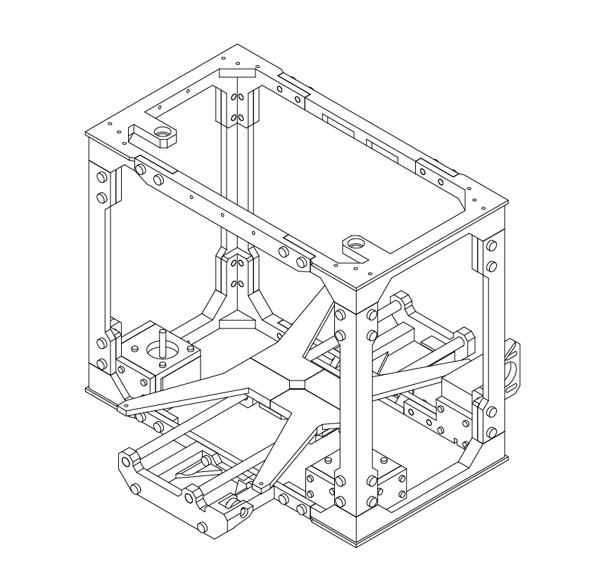
Congratulations! You’ve completed the outside frame!
This frame makes up the structural elements of
your printer, and is the building block for the remaining elements!
You’ve done an awesome job, and I’m sure it looks
amazing!
Take a moment to relax and marvel at your feat of
engineering, we’re going to be kicking it up a notch
in the next chapter!
B
2.4
6
SECTION
C
3.1 Extruder Assembly 34

1
2
C
3.1

Extruder Assembly
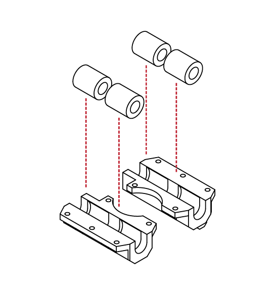
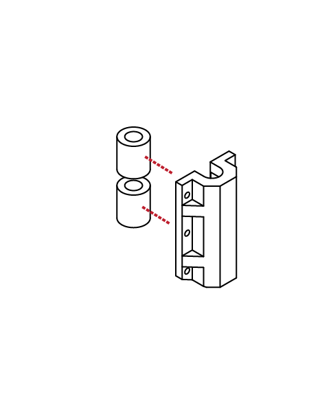
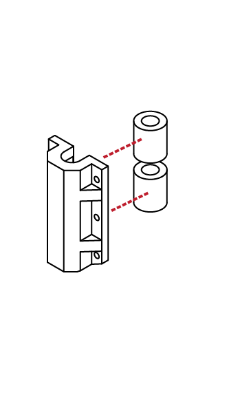
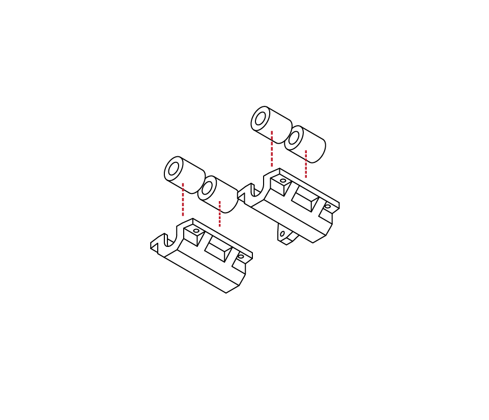
From the hardware kit, locate 4 LMS8UU linear bearings, and the 2 lower extruder bearing carriers. These can be identified by their semi circle cut outs.
Insert the bearings into the bearing carriers. Take care not to damage the bearings as they are inserted.
When fully inserted, the bearings shoul
protrude slightly fom the carriers.
Ensure that the bearings are aligned, and fully seated before proceeding to the next step.
N/A
N/A
X 10
M3 x 10
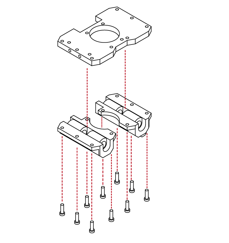
Locate the lower extruder base from the hardware kits.
From the hardware bag, select 10 M3 X 10 screws.
Align the lower bearing carriers with the extruder base. The semi circle cut-outs should align with the opening in the extruder base.
Using your hex wrench, install 5 of the screws into each of the bearing carriers, and into the extruder base.
C
3.1
3
4
5
C
3.1
Extruder Assembly
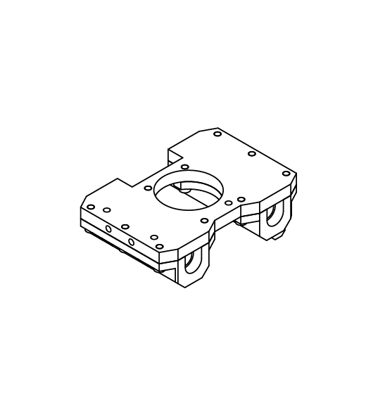
With the carriers mounted to the extruder base, check that the parts fit well and that there are no lose screws.
The bearings should be solidly captured and should not rattle or move once the pieces are assembled.
Locate your hot-end from the parts kit. We will be wiring and installing the remainder of its components later in this build.
Locate the hot-end mounting plate from your hardware kit as well.
Insert the hot-end into the mount.
The flange on the hot-end should seat snuggly up against the lower mount.
N/A
N/A
Check that there is not any excessive play in the mount.
If there is any play in the mount, use a small piece of tape on the mount to shim the
hot-end.
If the play is excessive, contact us for
a replacement or solution.
N/A
Select 2 M3 X 10 screws from your hardware set.
Install the screws into the hot-end mount, and into the extruder base.
Ensure that the mount is securely attached to the lower frame assembly.
X 2
M3 x 10
C
3.1
6
7
8
9
C
3.1
Extruder Assembly
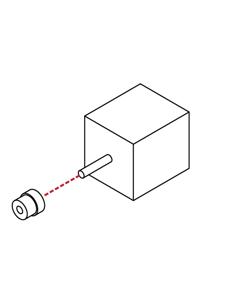
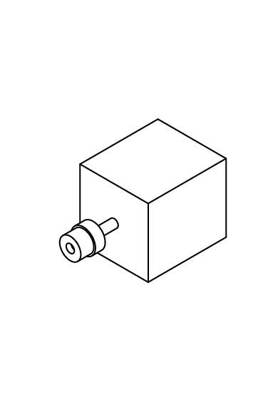
From the hardware kit, select one of the remaining 48mm stepper motors, as well as the MK8 extruder gear and the included grub screw.
Place the extruder drive gear onto the shaft of the stepper motor.
Use the small hex wrench to slightly tighten the grub screw to hold the gear in place.
We will need to fine-tune the gear’s location later in this guide, so do not tighten the screw completely.
N/A
N/A
X 3
M3 x 10
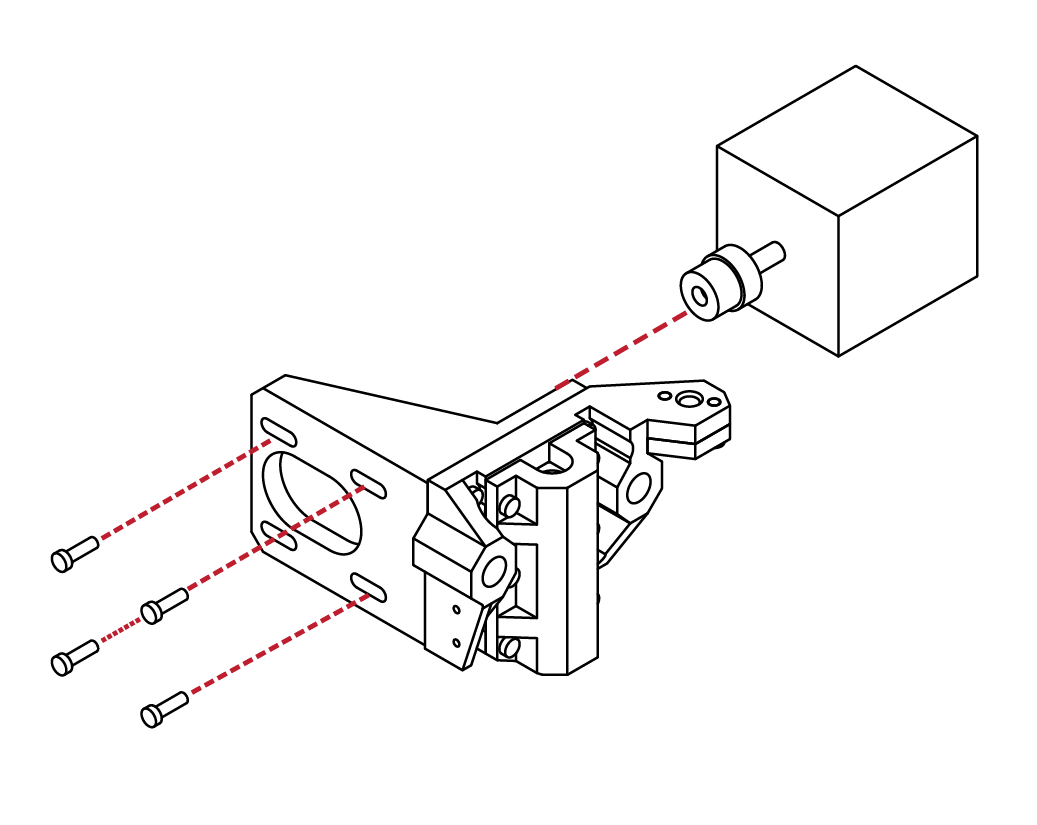
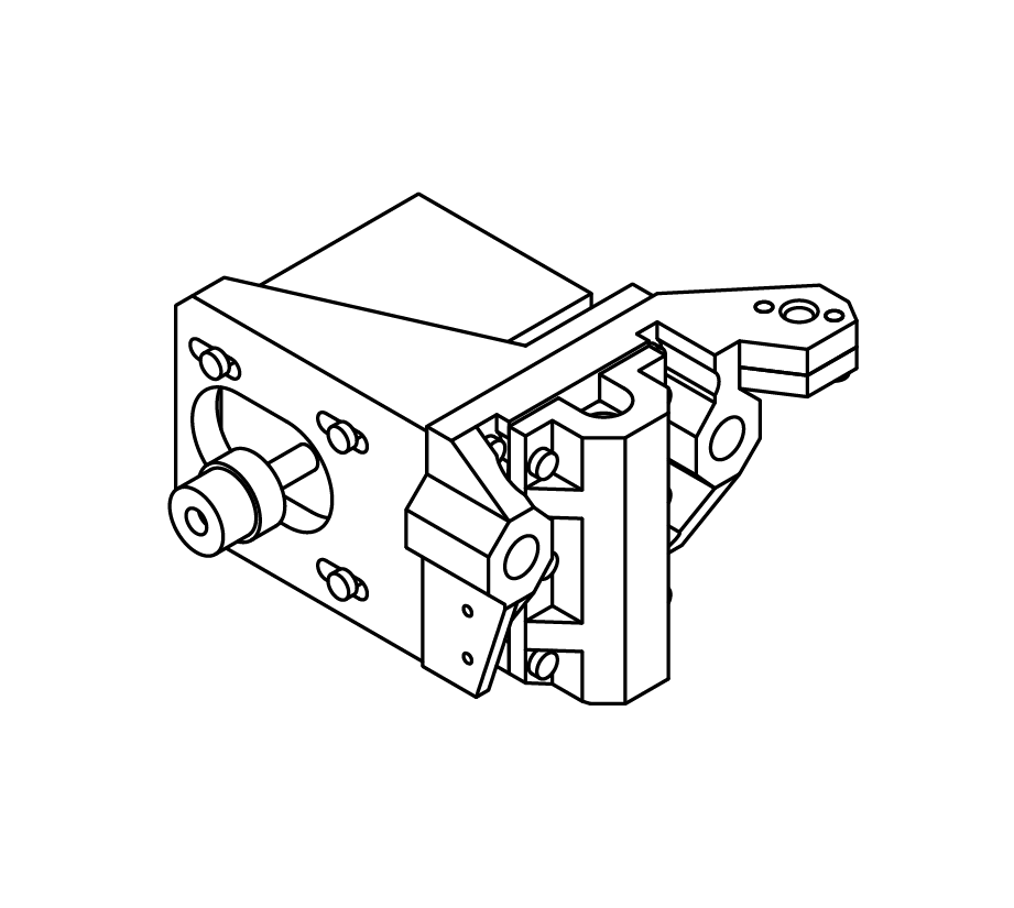
Locate the upper extruder mount from the hardware kit, and 3 M3 X 10 screws.
Insert the stepper motor into the extruder mount.
Take note to orientate the position of the motor such that the wire connectors are facing upwards.
Insert the 3 M3 X 10 screws through the extruder mount and into the stepper motor.
C
3.1
9
10
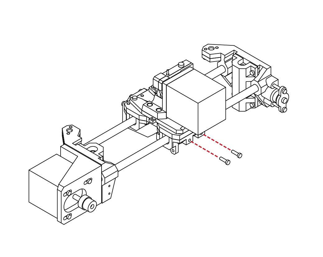
C
3.1
Locate 2 M3 X 10 screws and 1 M3 X 20 screws.
Take the lower extruder assembly and the upper
extruder assembly from the previous steps and mate them together. The screw holes should align.
Insert the M3 X 20 screw into the right-rear hole, and
the 2 remaining screws into the other openings.
Check that the screws are tight, and that the mount is secure. The hot-end should also be firmly in place with
no slop or play.
Extruder Assembly
X 2
X 1
M3 x 20
M3 x 10
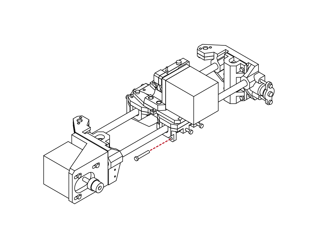
Locate both the front and rear extruder
arm components, as well as 2 M3 X 10,
and 1 M3 X 20 screws.
Place the two arm components face to face. The screw holes should align.
Insert the M3 X 10 screws into the arms to
secure them together. Place the M3 X 20 screw into the last opening.
X 2
X 1
The extruder arm is almost complete. Check that all the screws are tight and that the parts fit correctly.
N/A
M3 x 20
M3 x 10
C
3.1
11
12
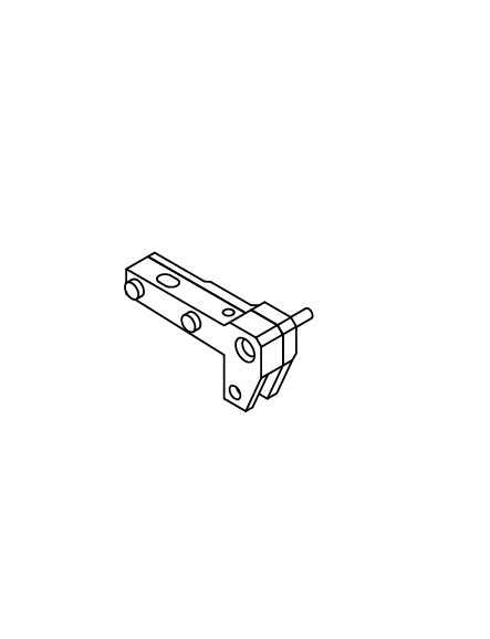
13
14
C
3.1
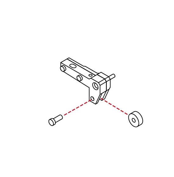
Extruder Assembly
Locate 1 radial ball bearing and 1 M4 X 10 screw from the hardware kit.
Insert the bearing into the opening of the extruder arm, and using your hex wrench install the screw into the arm, and through the bearing.
When tight, the bearing should still rotate freely.
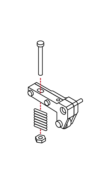
Locate 1 M4 X 40 screw, 1 compression spring, 2 washers, and one M4 nut.
Place the screw through the extruder
arm, afterwards place one washer, the
compression spring, a second washer,
and finally the nut onto the screw.
Thread the nut partially compress the spring.
X 1
X 1
M4 x 40
M4 x 10
N/A
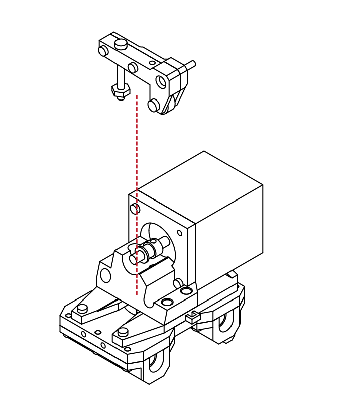
Using the extruder assembly from the previous step,
take the completed extruder arm and place it onto the extruder assembly.
The longer screw on the extruder arm should slot into
the base of the extruder. The flat faces of the nut
should also match the side of the extruder base as well.
C
3.1
15
16
17
C
3.1
Extruder Assembly
Insert a washer between the extruder arm and extruder assembly.
Screw the last M3 X 20 screw from the
extruder arm into the extruder assembly
and stepper motor.
The arm should move freely. By tightining or loosening the extruder spring screw, you can adjust the tension between the extruder gear and idler bearing. For now, set the tension so that the idler bearing is pressing against the extruder gear.
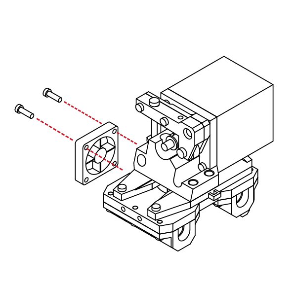
Select one of the 30mm cooling fans from your parts kit, and 2 M3 X 16 screws.
Using your hex wrench, attach the cooling fan to the side of the extruder assembly.
The cooling fan should sit flush with the
extruder assembly.
N/A
X 2
M3 x 16
X 2
X 2
M3 x 16
M3 x 10
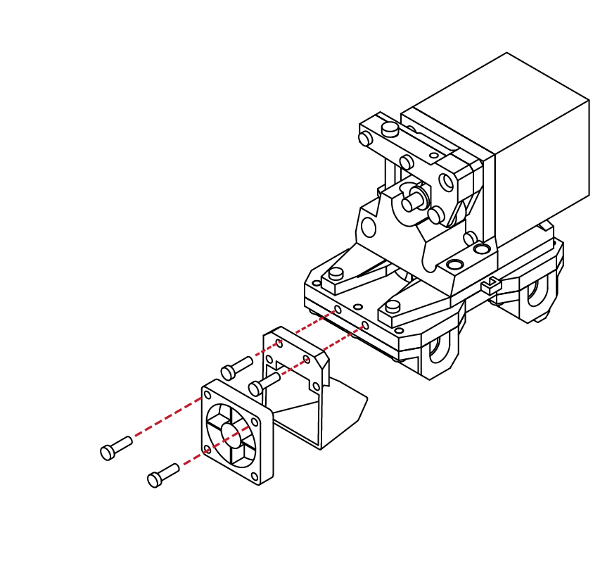
Select one of the 30mm cooling fans, and the fan duct from your parts kit.
Select 2 M3 X 16 and 2 M3 X 10 screws from your
hardware kit as well.
Attach the cooling fan to the fan duct using the M3 X 16 screws, and attach the fan duct to the extruder assembly using the M3 X 10 screws.
C
3.1
18
SECTION
D
4.1 X Carriage Assembly 48
4.2 Y Carriage Assembly 62
4.3 Print Bed Installation 76
4.4 Z Carriage Assembly 82

1
2
D
4.1
X Carriage Assembly
Locate the Z Axis bearing holders from your parts kit, and 2 linear bearings from the
hardware kits.
The Z axis bearing holders are identified by their 6 screw holes and slight chamfer on the leading edge.
Press the linear bearings into the bearing carrier and ensure that they are fully seated and aligned.
Fromy your parts kit, locate the left X axis mount. The left X axis mount is identifiable by its semi-circle idler mounts on the rear.
Press the bearings and bearing holders into the X axis mount.
Ensure that the bearings and bearing carrier are flush with the mount and insert the
6 M3 X 10 screws to secure the bearing and holder in place.
N/A
X 6
M3 x 10
The left X axis mount is now complete.
Check that the bearing holder is tight to the
X axis mount.
N/A
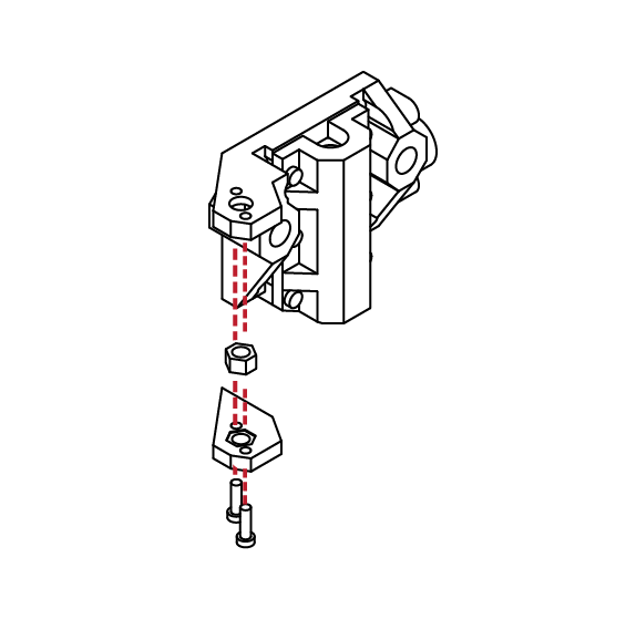
Locate one of the M4 nuts from the hardware kit along with 2 M3 X 10 screws, along with the Z axis capture plate.
Insert the nut into the X axis carriage.
Using your hex wrench, insert the screws into the capture plate, and then attach the plate to the X axis assembly.
Take care not to damage the X axis mount or over tighten the screws.
X 2
M3 x 10
D
4.1
3
4
5
6
D
4.1
X Carriage Assembly
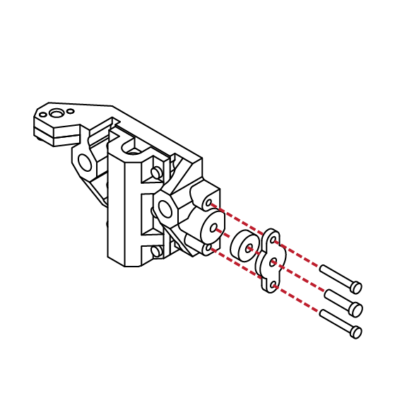
Take the completed X axis assembly and locate the idler bearing cover plate, along with 1 idler bearing, 1 M4 X 16 and 2 M3 X 20 screws.
Insert the screws through the cover plate, and place the idler bearing onto the M4 screw.
Using your hex wrench, screw the assembly into the X axis assembly.
The left X assembly is now complete. Check that the idler bearing spins freely, and that all screws are tight and secure.
X 2
X 1
N/A
M3 x 20
M4 x 16
Locate the Z Axis bearing holders from your parts kit, and 2 linear bearings from the
hardware kits.
The Z axis bearing holders are identified by their 6 screw holes and slight chamfer on the leading edge.
Press the linear bearings into the bearing carrier and ensure that they are fully seated and aligned.
N/A
Fromy your parts kit, locate the right X axis mount. Ensure that the bearings and bearing carrier are flush with the mount and insert the
6 M3 X 10 screws to secure the bearing and holder in place.
Locate one of the M4 nuts from the hardware kit along with 2 M3 X 10 screws, along with the Z axis capture plate.
Insert the nut into the X axis carriage.
Using your hex wrench, insert the screws into the capture plate, and then attach the plate to the X axis assembly.
X 6
M3 x 10
D
4.1
7
8
9
D
4.1
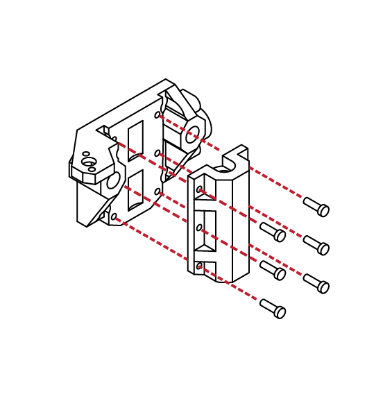
Locate the X axis motor mount, and right X axis mount. From your hardware kit, select 4 M3 X 10 screws.
Align the X axis mount with the motor mount, and using your hex wrench install the 4 screws.
Ensure that the motor mount is flush and tight with the X axis mount.
X Carriage Assembly
X 4
M3 x 10
From the hardware kit, select one of the remaining 48mm stepper motors, as well as the GT2 Pulley.
N/A
Place the GT2 Pulley onto the shaft of the stepper motor.
Use the small hex wrench to slightly tighten the grub screw to hold the gear in place.
We will need to fine-tune the pulley’s location later in this guide, so do not tighten the screw completely.
N/A
D
4.1
10
11
12
D
4.1
From your hardeare kit, locate 4 M3 X 10 screws, and gather the stepper motor and X axis assembly from the previous steps.
Insert the stepper motor into the motor mount. Ensure that the cable connector on the motor is facing upwards.
Using your hex wrench, insert the 4 M3 X 10 screws into the motor mount and into the stepper motor. We will be adjusting the motor tension later in this guide, so there is no need to completely tighten the screws.
X Carriage Assembly
X 4
M3 x 10
N/A
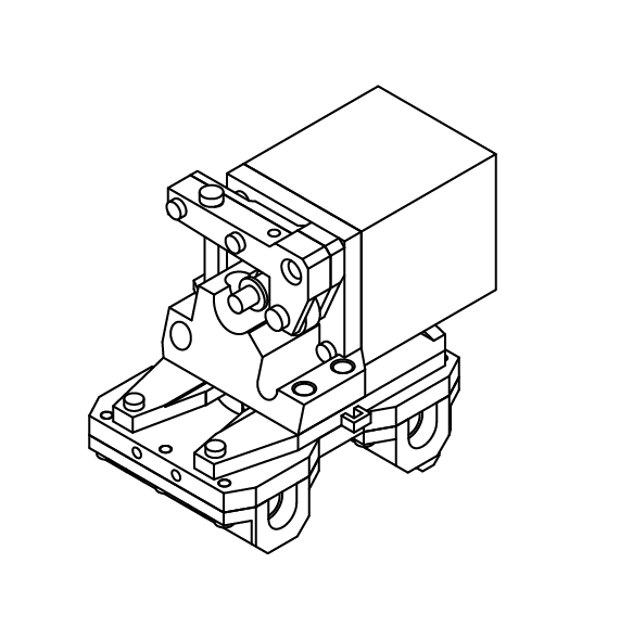
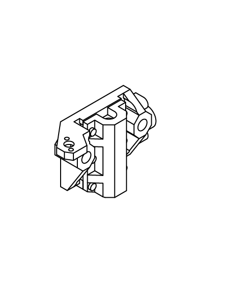
Congratulations! You’ve completed the X motor
assembly.
Take a moment to ensure that all the scews and parts fit correctly and are tight.
D
4.1
13
14
D
4.1
Locate the left X assembly from the previous steps as well as 2 250mm linear rod.
These rods are the same length as the rods used for the Z axis, but shorter than those used for the Y axis. Using a soft mallet, gently drive the rods into the X assembly.
Take care to ensure the rods are inserted square to the assembly and that you do not damage the X axis
assembly. When fully inserted, the rods should rest against the small openings on the backside of the
X axis assembly.
X Carriage Assembly
N/A
X 2
X 1
M3 x 20
M3 x 10
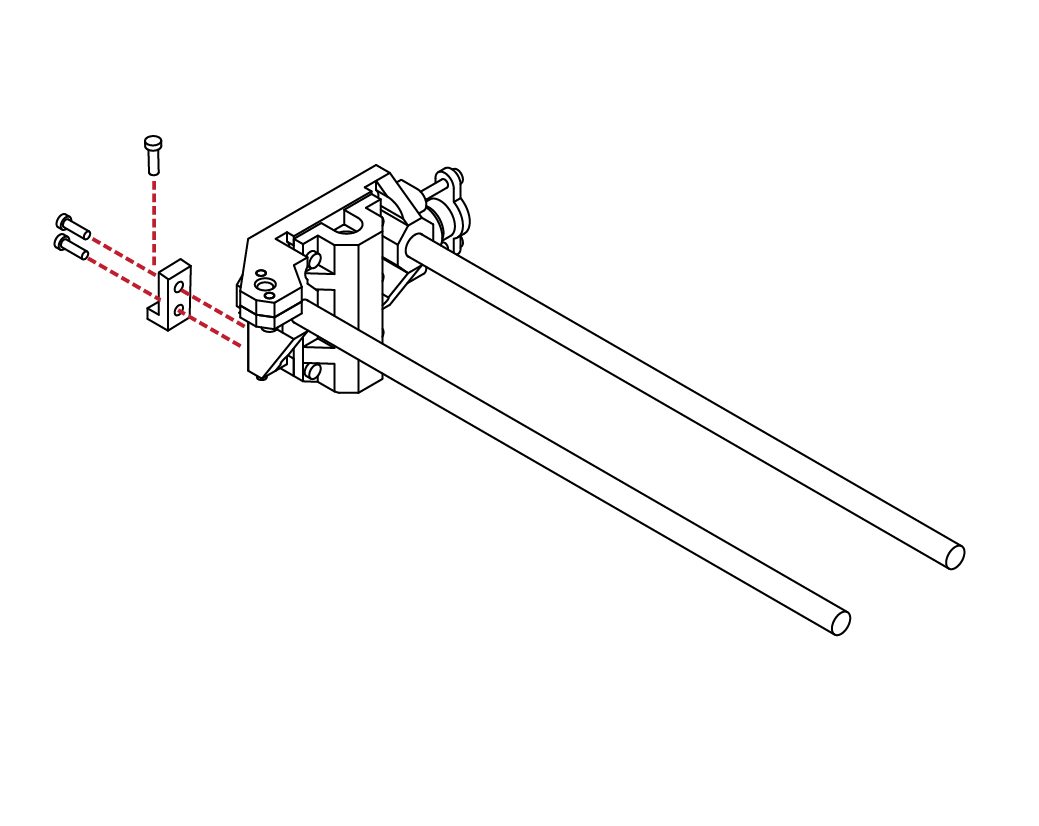
Locate the Z Axis screw mount from your parts kit, along with 2 M3 X 10, and 1 M3 X 20 screws.
Using your hex wrench, attach the Z axis screw mount to the outside of the X axis assembly.
Take the remaining M3 X 20 screw and screw it partially through the mount. This will be used to level your initial layer height later on.
D
4.1
15
16
D
4.1
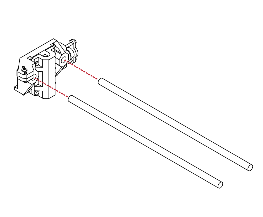
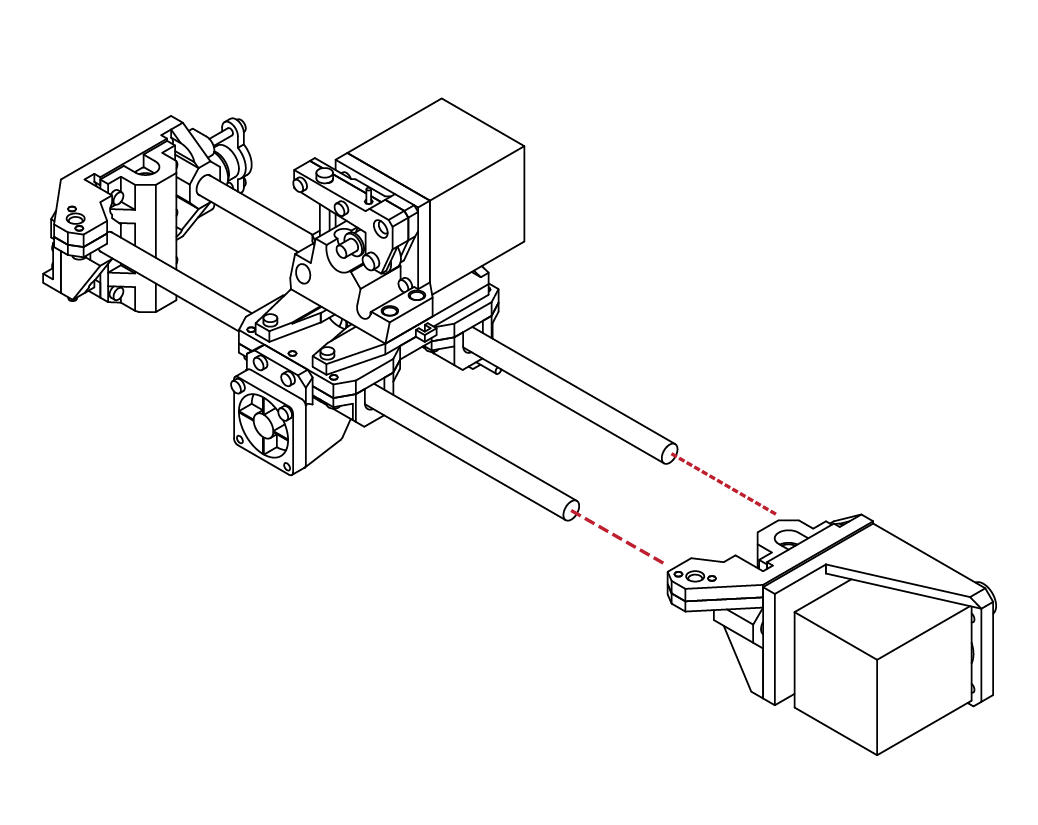
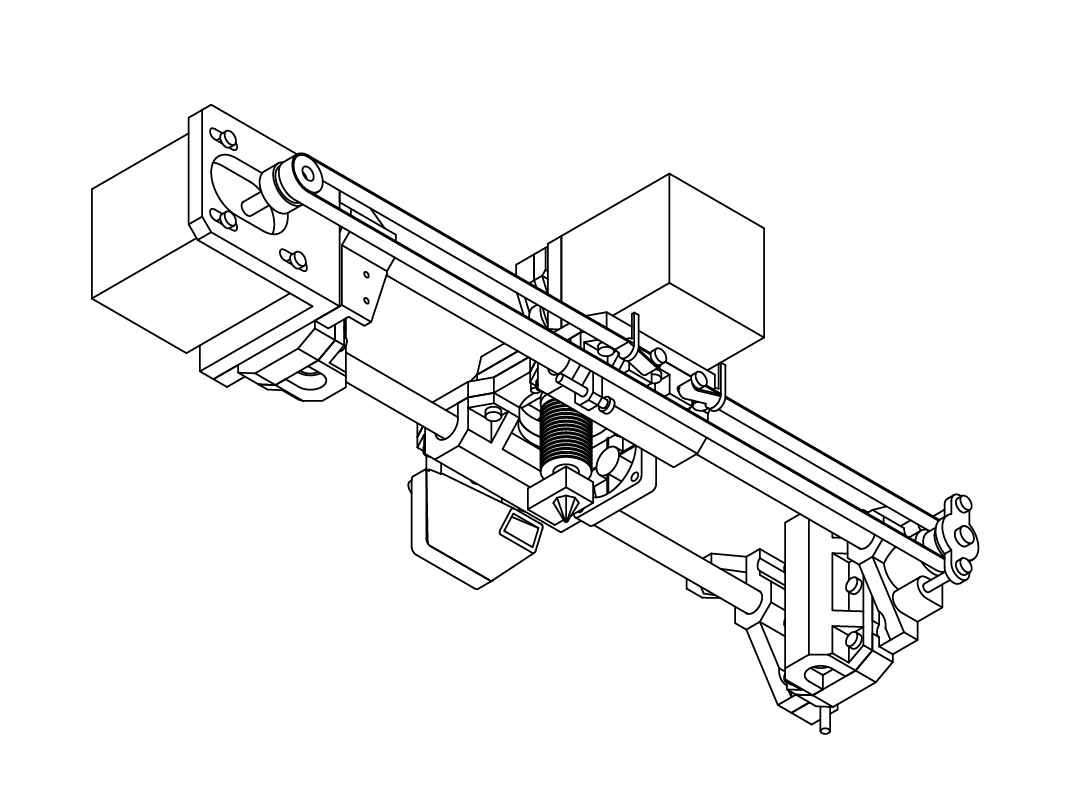
Locate the Extruder assembly that we assembled earlier in this guide.
Orientate the extruder so that the hot-end cooling fan is facing the X axis assembly.
Carefully slide the extruder assembly onto the linear rods.
Be careful when doing so, as it is easy to mis-align the rods, and damage the bearings.
X Carriage Assembly
N/A
N/A
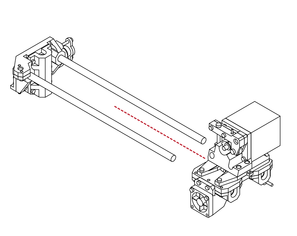
With the extruder assembly in place, collect the right
X axis assembly that we assembled earlier.
Using a soft mallet, gently insert the X axis assembly onto the linear rods.
Take care not to damage the X assembly or linear rods.
If you find it particularily difficult, you can remove the 4 screws holding the motor assembly, and use the backside of X axis to hammer against directly. The linear rods should be flush with the backside of the X axis assembly.
D
4.1
17
18
D
4.1
From your hardware kit, select 2 M3 X 10 screws.
Using your hex wrench, insert the screws into the
backside of the extruder assembly.
The screws should sit roughly 6mm proud of the extruder assembly. These will be used later in this guide to secure the GT2 belts.
X Carriage Assembly
X 2
M3 x 10
X 1
M3 x 20
Locate 1 M3 X 20 screw from your hardware kit.
Using your hex wrench, insert the screw partially
into the extruder assembly.
This screw will be used later to adjust your X axis
end-stop.
D
4.1
19
1
D
4.2
Locate the lower Y bearing carriers, and 4 linear
bearings from your parts kit.
Insert the bearings into the bearing carriers.
Ensure that the bearings are fully seated before
proceeding.
Y Carriage Assembly
N/A

N/A
Gather the 4 lower Y bed pieces from your parts kit and arrange them like so.
D
4.2
2
3
D
4.2
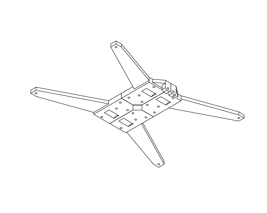
Arrange the lower Y bed pieces such that the
indentations for the bearings align.
Ensure that the pieces fit well.
You may use a sharp Exacto-knife or file to trim any parts that do not fit well.
Y Carriage Assembly
N/A
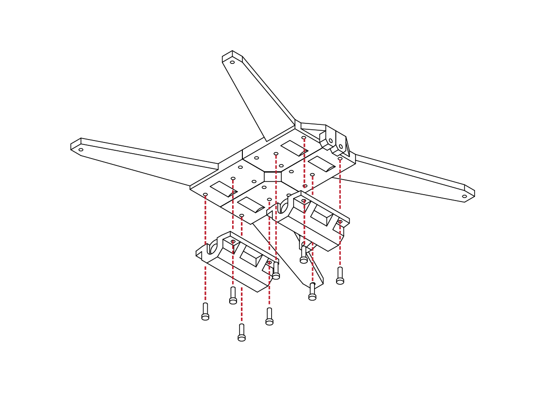
X 8
M3 x 10
From your hardware kit, locate 8 M3 X 10 screws. Gather the bearing carriers that were assembled previously.
Using your hex wrench, install the 8 screws into the
bearing carriers, and then into the Y bed frame
components.
D
4.2
4
5
D
4.2
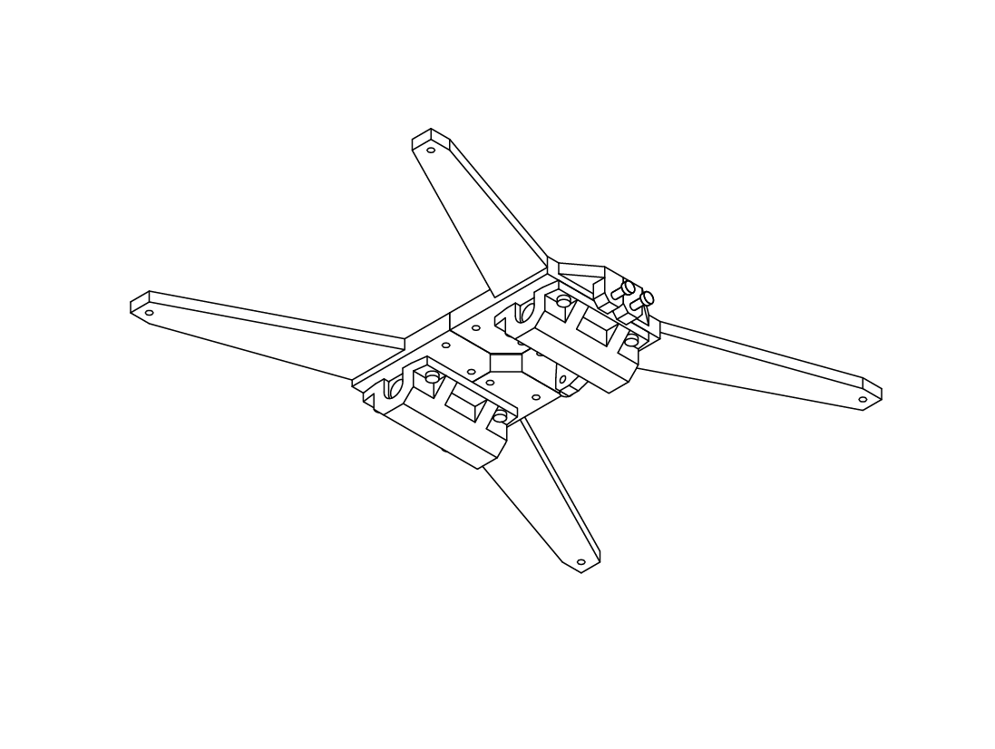
Ensure that all parts fit correctly and that all screws
are tight.
The bearings should be firmly captured in their carriers and should have little play in them.
Y Carriage Assembly
N/A
X 8
M3 x 10
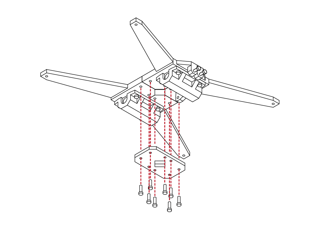
Locate the Y bed cross member from your parts kit, along with 8 M3 X 10 screws.
Using your hex wrench, install the screws into the cross member, and then into the lower bed assembly.
D
4.2
6
7
D
4.2
With the cross member installed, ensure that all parts fit well and that all screws are tight.
Y Carriage Assembly
N/A
X 2
M3 x 10
Locate 2 M3 X 10 screws from your hardware kit.
Insert the screws into the 2 mounting points on the side of the lower bed.
The screws should sit 6mm proud of the mount.
These screws will be used to secure the GT2 belt to later in this guide.
D
4.2
8
7
D
4.2
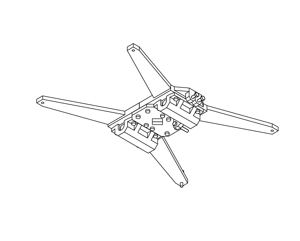
Locate 1 M3 X 20 screw from your hardware kit and install it into the screw mount on the rear of the lower bed assembly.
This screw will be used to home the bed later in your configuration.
Y Carriage Assembly
X 1
M3 x 20
N/A
Congratulations! The lower bed assembly is complete!
Double check that all the fasteners are tight and that all the parts are properly aligned.
D
4.2
8
9
10
D
4.2
Y Carriage Assembly
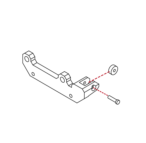
From your parts kit, locate the front Y axis carrier. Locate 1 bearing and 1 M4 X 16 screw from your hardware kit.
Insert the bearing into the bearing holder, and using youe hex wrench, insert the screw into the bearing holder and bearing.
Ensure that the bearing can rotate freely in its holder.
This bearing will act as the idler for the GT2 belt which will be installed later in this guide.
N/A
X 1
M4 x 16
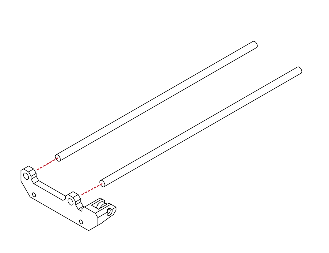
N/A
Locate the longest linear rods from your hardware kit.
Using a soft mallet, gently insert the linear rails into the
Y axis carrier.
Take care to ensure the rods are square and that the
carrier is not damaged.
When fully inserted, the face of the rods should be flush with the face of the carrier.
D
4.2
11
12
D
4.2
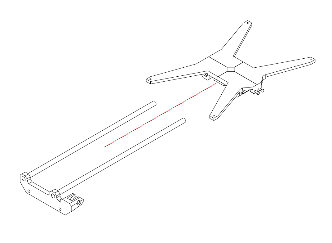
Take the lower Y bed from the previous steps and
carefully insert the lower Y carriage assembly.
Take care when guiding the linear rods through
the bearings.
The bearings can easily be damaged if the rods are
mis-aligned or excessive force is used when inserting them into the bearings.
Y Carriage Assembly
N/A

N/A
Locate the rear Y carrier from your parts kit.
Using a soft mallet, gently insert the carrier onto the
existing assembly.
Take care to not damage the rear carrier.
When fully inserted, the faces of the linear rods should
be flush with the face of the rear carrier.
D
4.2
13
1
D
4.3
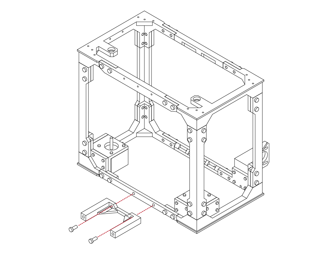
Take the front Y axis mount from your parts kit, and
gather 2 M5 X 12 screws.
Using your hex wrench, attach the Y axis mount to the front frame of the printer.
Ensure that the screws are tight and that the parts fit correctly.
Print Bed Installation
X 2
M5 x 12
X 2
M5 x 12
Repeat the same procedure for the rear, using the
rear Y axis mount and 2 M5 X 12 screws.
Ensure that the part is tight to the frame and that both screws are tight.
D
4.3
2
3
D
4.3
Congratulations, the front and rear Y axis mounts are installed.
Before proceeding, double check that all connections
are tight and that the parts fit correctly.
Print Bed Installation
N/A
N/A
Locate the lower bed assembly that we completed
earlier in this guide.
Insert the lower bed assembly into the frame of the printer, and over top of the Y axis mounts.
If everything aligns, the lower bed assembly should drop into place on the Y axis mounts.
If the lower bed does not fit, or there is uneccessary force needed to fit it, use a soft mallet on the inside of the
Y axis carriers to lengthen them slightly and try again.
D
4.3
4
5
D
4.3
Locate 4 M5 X 12 screws from your hardware kit.
Using your hex wrench, install the screws through the
Y axis carriers and into the Y axis mounts.
Print Bed Installation
X 4
M5 x 12
N/A
Congratulations! The lower bed installation is complete.
Double check that the screws are secure and that
everything aligns properly.
Your printer should sit flat with little or no ‘wobble’.
If there is any issues you may readjust the lower Y mount until suitable.
D
4.3
6
1
D
4.4
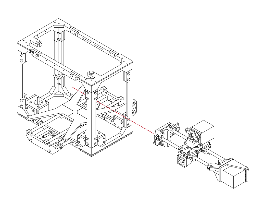
With the lower bed installed, locate the
X axis assembly completed previously in this guide.
Insert the X axis assembly through the side of the frame.
The front of the extruder should face the front of the frame as well.
Z Carriage Assembly
N/A
N/A
With the X axis assembly in the frame, it is advised that you temorarily secure the X axis to the top of the frame using cable ties or similar.
D
4.4
2
3
D
4.4
Locate the Z axis carriers from your parts kit, along with the remaining 2 linear rods.
Using a soft mallet, insert the linear rods into the carriers.
When fully inserted, the face of the rod should be flush with the face of the carrier.
Z Carriage Assembly
N/A
N/A
Take the Z axis rods and carriers assembled in the
previous step and insert them through the bottom of the frame.
Insert the linear rods into the X axis assembly, taking care to not damage the linear bearings.
D
4.4
4
5
D
4.4
With the Z rods in place, check that there is no binding
of the X axis and that everything is aligned before
proceeding to the next step.
Z Carriage Assembly
N/A
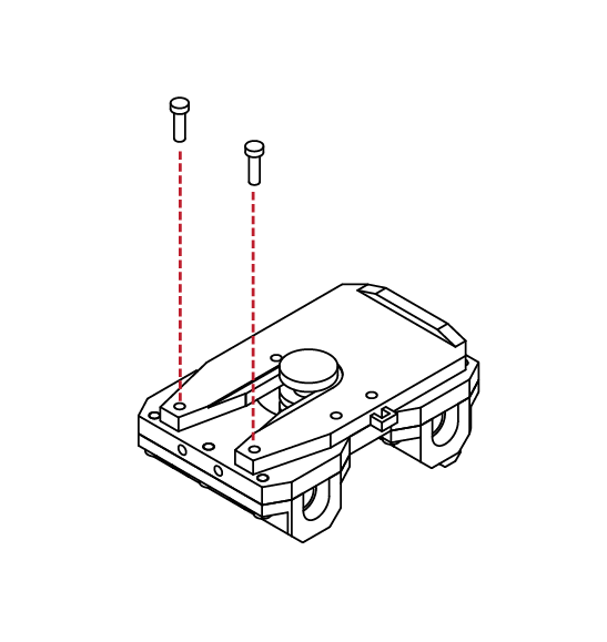
X 2
M3 x 10
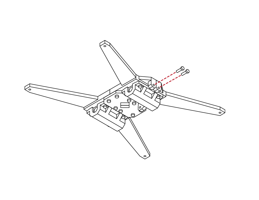
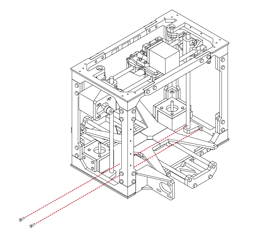
Gather 2 M3 X 10 screws from your hardware kit.
Using your hex wrench, install both screws through the ears of the Z axis mount and into the side of the frame.
Take care to ensure that the mount is tight against the frame and that the fasteners are secure.
D
4.4
6
7
D
4.4
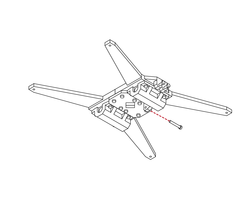
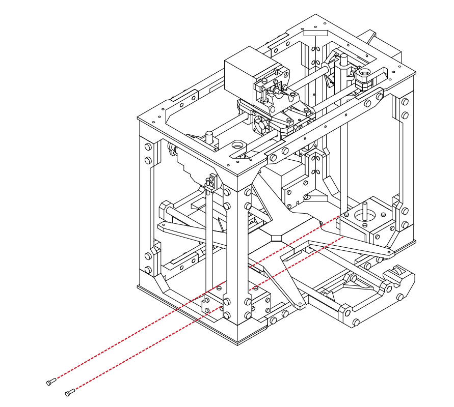
Repeat the same procedure in the last step, securing the opposite Z mount using 2 M3 X 10 screws.
Z Carriage Assembly
X 2
M3 x 10
N/A
With the lower Z mounts secured to the frame, locate
the remaining 2 Z mounts from your parts kit.
Using a soft mallet, gently install the 2 mounts onto
the linear rods.
When properly installed, the face of the Z mounts
should be flush with the face of the linear rods.
D
4.4
8
9
D
4.4
Similar to the previous steps, locate 2 M3 X 10 screws and secure the top Z mounts. Ensure that the mounts are flush with the frame and that the fasteners are secure.
Z Carriage Assembly
X 2
M3 x 10
X 2
M3 x 10
Repeat the same procedure for the opposite Z mount. Ensure that mount is flush with the frame, and that the fasteners are secure.
D
4.4
10
11
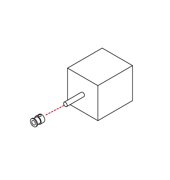
D
4.4
From your parts kit, locate the Z couplers.
Slide these couplers onto the shaft of the Z axis stepper motors.
Using your hex wrench, tighten the set screw on the coupler to secure it to the shaft.
Z Carriage Assembly
N/A
N/A
Ensure that the coupler is positioned half way onto the shaft.
The threaded rod will attach to these couplers in the following steps.
D
4.4
12
13
D
4.4
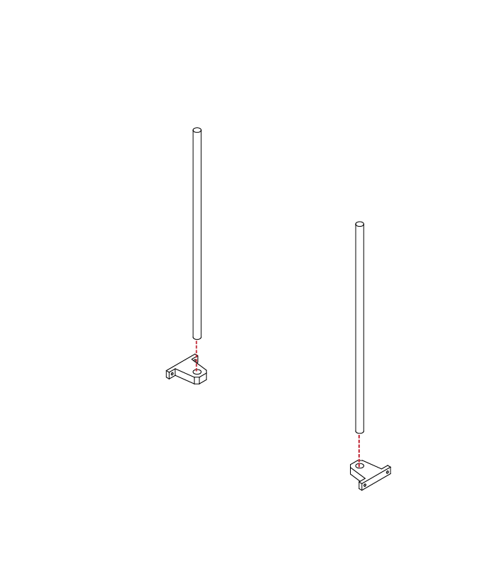
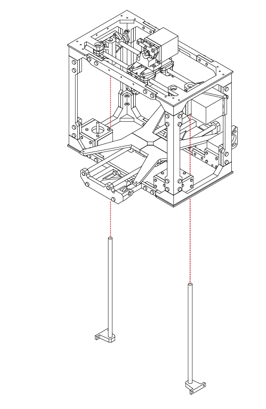
Locate the threaded rods from your parts kit.
Insert the rods through the top of the frame and thread the rods through the X axis mounts and into the couplers installed previously.
Using your hex wrench, tighten the set screws on the couplers to secure the threaded rod.
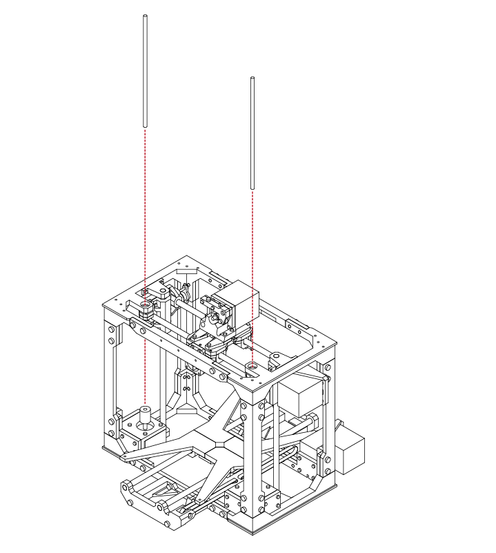
Z Carriage Assembly
N/A
N/A
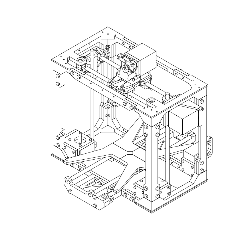
With both rods secure, check that the X axis is level.
If the X axis is uneven, simply turn either one of the threaded rods to raise or lower the axis until it appears close to level.
D
4.4
14
SECTION
E
5.1 GT2 Belt Installation 98
5.2 LCD Installation 102
5.3 RAMPS Installation 106
5.4 Upper Bed Installation 116
5.5 Wiring & Final Configuration 118

1
E
5.1
From your hardware kit, locate the GT2 Belts.
If not already cut, cut the belt to length so that it is long enough to loop around the motor, and opposite idler bearing with some extra length.
The belt will be mounted with the teeth facing inwards.
Take one end of the belt and loop it around one of the screws on the extruder assembly.
GT2 Belt Installation
N/A
Secure this using a cable tie so that the belt teeth mesh together. Take the belt and loop it around the idler bearing and back around the pulley on the X axis motor.
Your belt should be long enough to reach the
remaining screw on the extruder assembly.
While holding the extruder assembly in place, use a pair of pliers, or a second set of hands to pull the belt as tight as possible to remove any slack.
With the slack removed, secure the belt to the screw using the same method as before.
When complete, the belt should be tensioned and tight. If there is slack, you may loosen the 4 screws holding the motor in place and slide it backwards, away from the frame to tension the belt more.
Remember to tighten the motor mounts when complete.
E
5.1
2
3
E
5.1
We will now complete the same procedure for the Y axis.
If not already cut, cut the belt to length so that it is long enough to loop around the motor, and opposite idler bearing with some extra length.
The belt will be mounted with the teeth facing inwards.
Take one end of the belt and loop it around one of the screws on the lower bed assembly.
GT2 Belt Installation
N/A
Secure this using a cable tie so that the belt teeth mesh together. Take the belt and loop it around the idler bearing and back around the pulley on the Y axis motor.
Your belt should be long enough to reach the
remaining screw on the lower bed assembly.
While holding the extruder assembly in place, use a pair of pliers, or a second set of hands to pull the belt as tight as possible to remove any slack.
With the slack removed, secure the belt to the screw using the same method as before.
When complete, the belt should be tensioned and tight. If there is slack, you may loosen the 4 screws holding the motor in place and slide it backwards, away from the frame to tension the belt more.
Remember to tighten the motor mounts when complete.
E
5.1
4
1
2
E
5.2
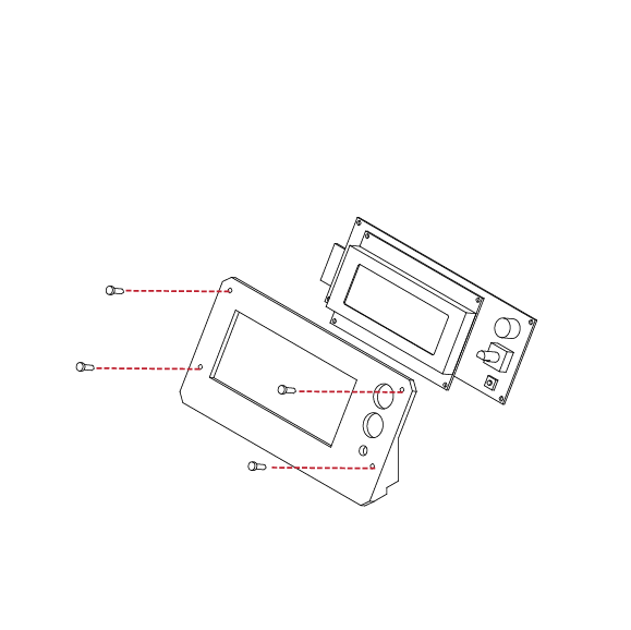
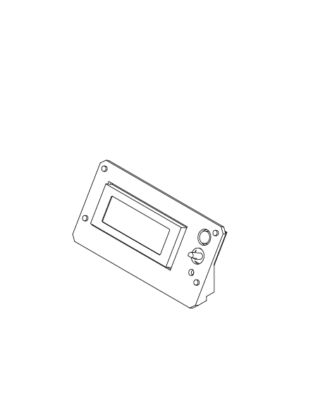
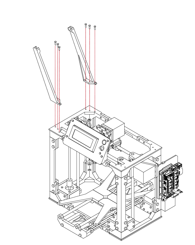
LCD Installation
Locate the LCD display from your electronics kit, along with 4 M3 X 20 screws, and the LCD display mount from your printed parts kit.
Remove the control nob from the LCD display by pulling straight up on it.
Using your hex wrench, insert the 4 screws into the LCD frame, and then into the LCD display.
Use 4 M3 nuts to secure the lcd display to the frame.
Take care to not distort the LCD frame or damage any components when installing the screws.
Re-attach the control nob onto the
LCD display.
N/A
X 4
M3 x 20
N/A
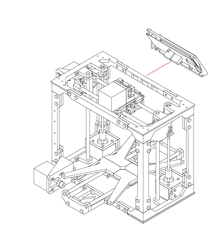
The LCD frame will affix to the front of the upper frame chassis.
Check to ensure that the frame and LCD panel will fit correctly before proceeding.
E
5.2
3
4
E
5.2
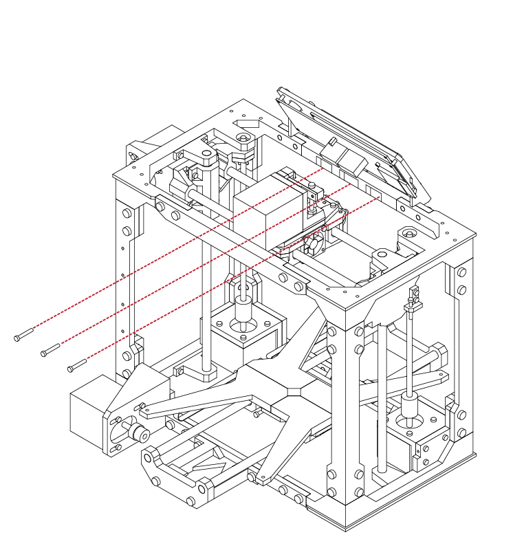
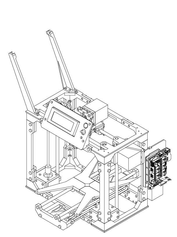
Locate 3 M3 X 10 screws from your hardware kit.
With the LCD assembly in place, use your hex wrench to insert the screws into the rear of the upper frame, and secure the LCD panel in place.
LCD Installation
X 3
M3 x 10
N/A
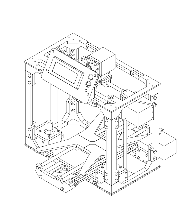
With the LCD assembly in place, ensure that it is secure and that it fits well.
Ensure all fasteners are tight.
E
5.2
5
6
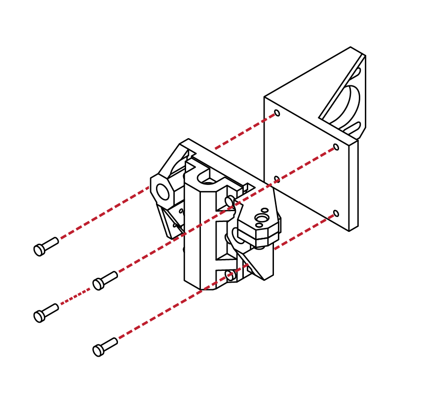
E
5.3
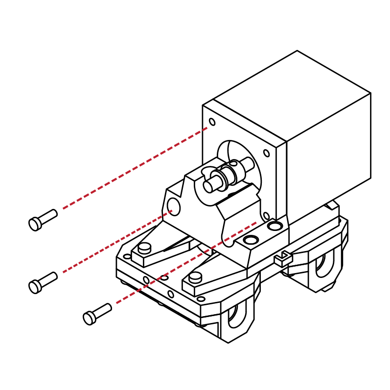
Locate the Electronics backplate from your printed parts kit, along with 4 M3 X 10 screws.
Using your hex wrench, insert the screws into the
backplate, and then secure the backplate to the rear upright frame.
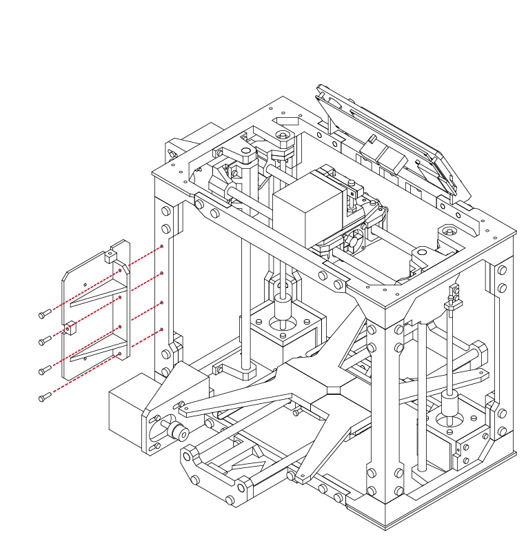
RAMPS Installation
X 4
M3 x 10
N/A
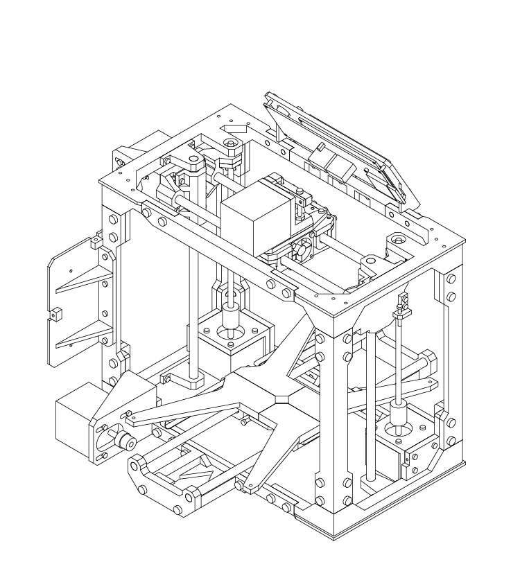
With the backplate in place, ensure that the plate is
tight to the frame, and that all fasteners are secure.
E
5.3
7
8
E
5.3
Locate the Arduino Mega from your electronics kit.
This is easily identified by its blue colour board.
Using 3 M3 X 10 screws, attach the Arduino to the
electronics backplate.
Take care to ensure that the Arduino is not bent or
mis-aligned.
The board does not need to be absolutely tight,
just secure.
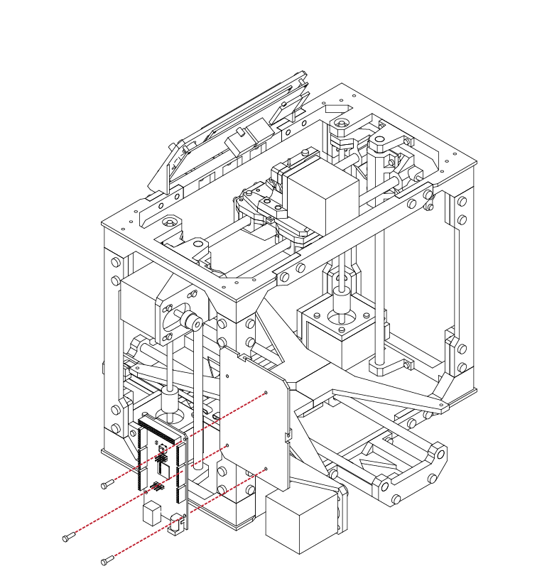
RAMPS Installation
X 3
M3 x 10
N/A
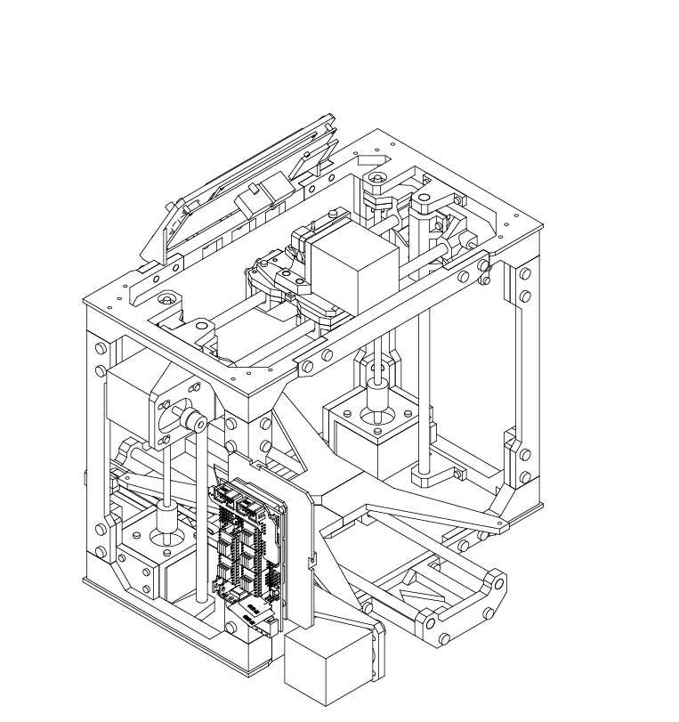
Gather the RAMPS 1.4 electronics board from your
hardware kit.
Carefully insert it onto the Arduino board we attached in the previous steps.
Take care to ensure that all of the pins lin up with their respective sockets, and that the board is fully seated.
E
5.3
9
1
E
5.3
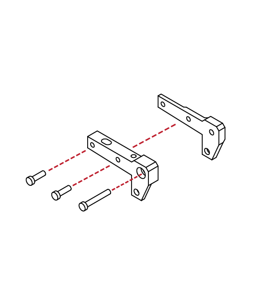
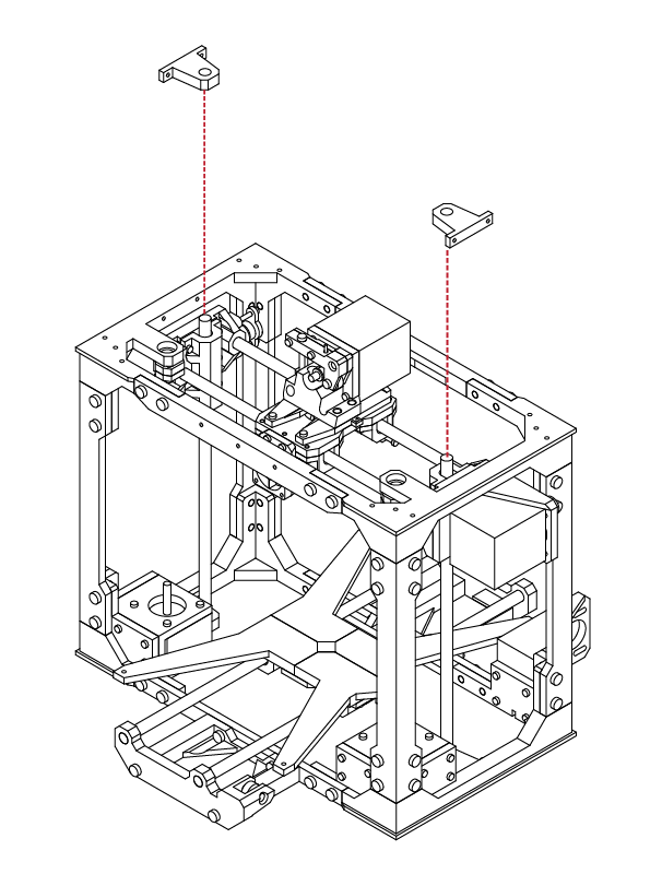
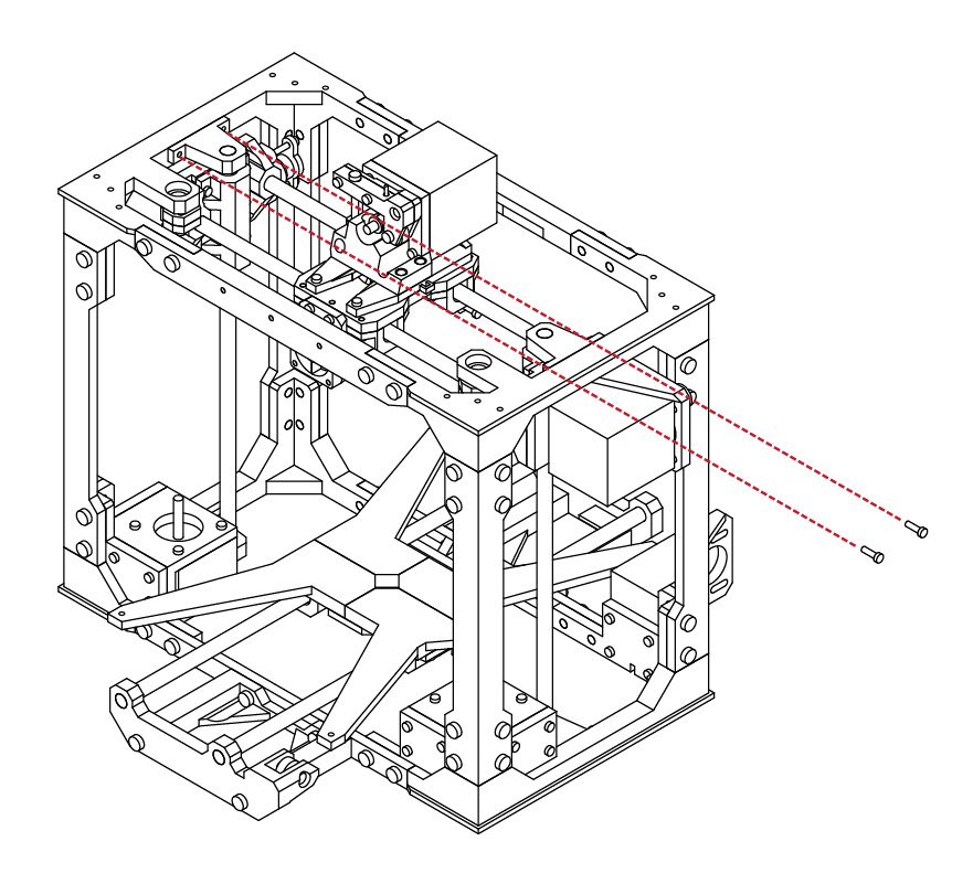
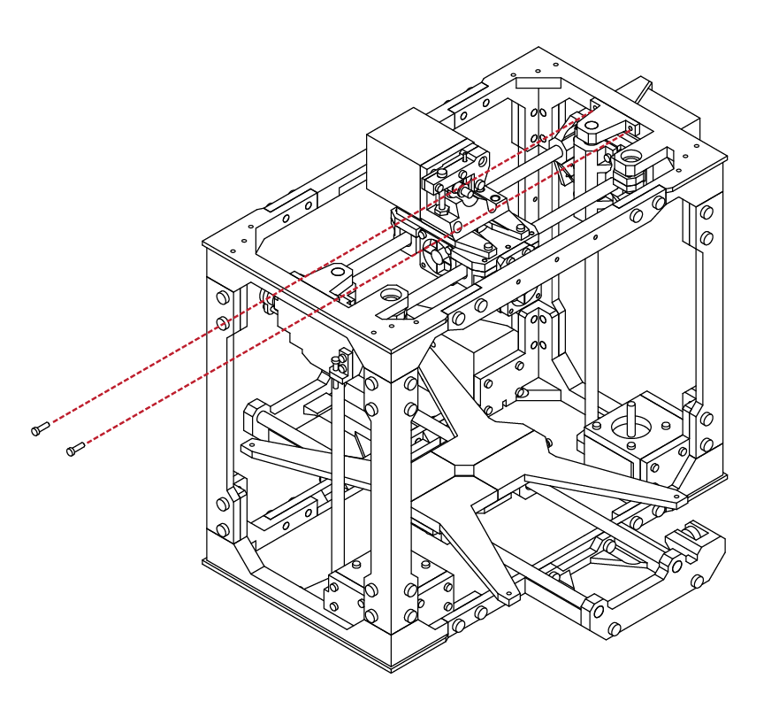
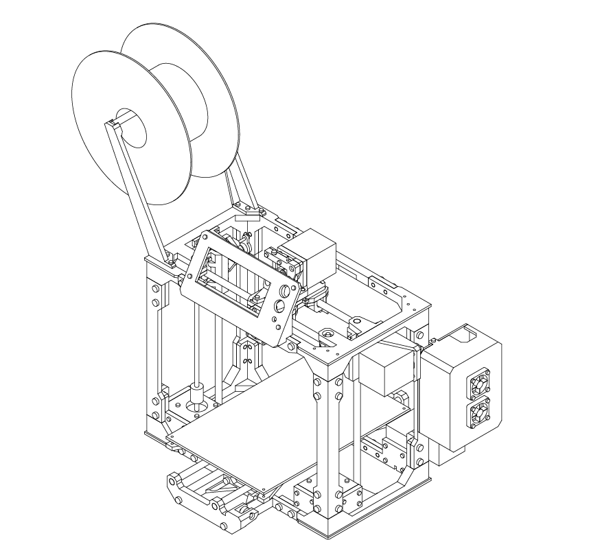
Locate the Spool holder mounts from your printed parts kit, along with 6 M3 X 10 screws.
The spool holder can be mounted on either side of the top frame.
Using your hex wrench, insert the screws into the spool holder mounts, and then into the top of frame.
Filament Spool Installation
X 6
M3 x 10
N/A
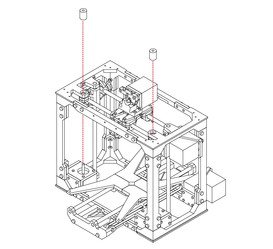
With the spool holder installed, you can use the
remaining short linear rod to hold the filament
spool in place.
E
5.3
2
10
E
5.3
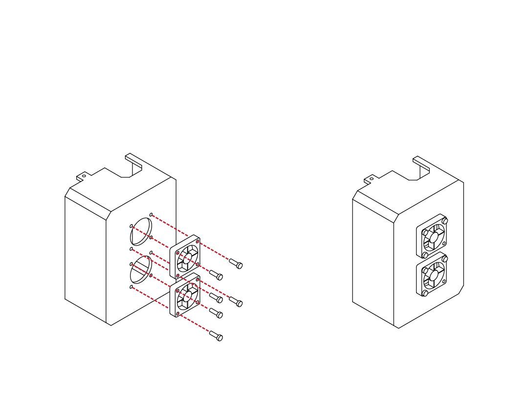
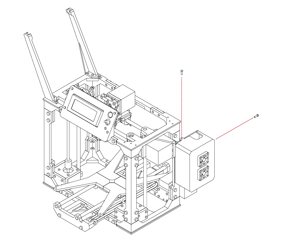
Locate the Electronics enclosure from your printed parts kit, along with 2 30mm fans, and 6 M3 X 16 screws.
Using your hex wrench, attach the fans to the outside of the enclosure.
Feed the fan wires through the remaining screw hole in the enclosure.
RAMPS Installation
X 6
M3 x 16
N/A
Check the fitment of the enclosure to the electronics back plate.
The tabs on the enclosure should align and fit with the back plate.
You may need to use a small exacto knife or file to trim the tabs if the enclosure does not fit correctly.
E
5.3
11
12
E
5.3
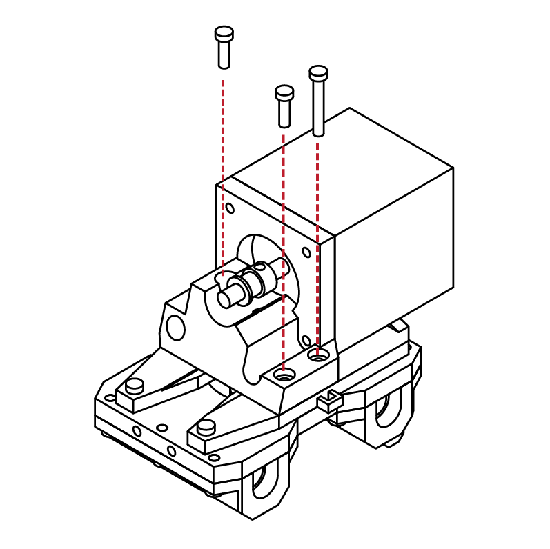
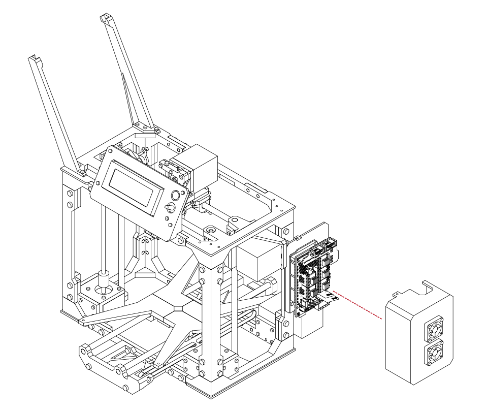
With the enclosure in place, use 2 M3 X 10 screws to secure the enclosure.
RAMPS Installation
X 2
M3 x 10
N/A
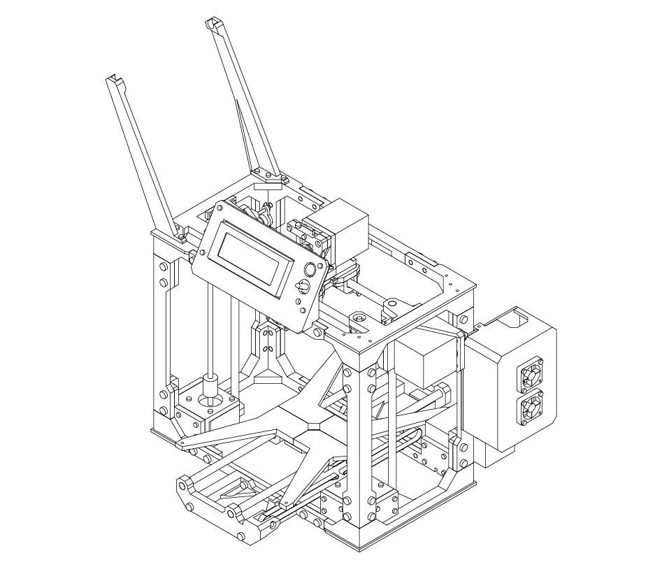
The electronics enclosure is now complete.
However, for the enxt steps we will need to remove the cover.
Refer to these steps to remove and reinstall the enclosure when completed.
E
5.3
13
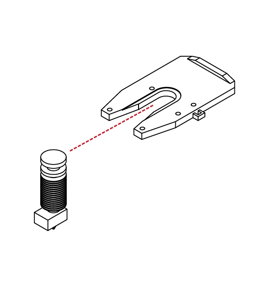
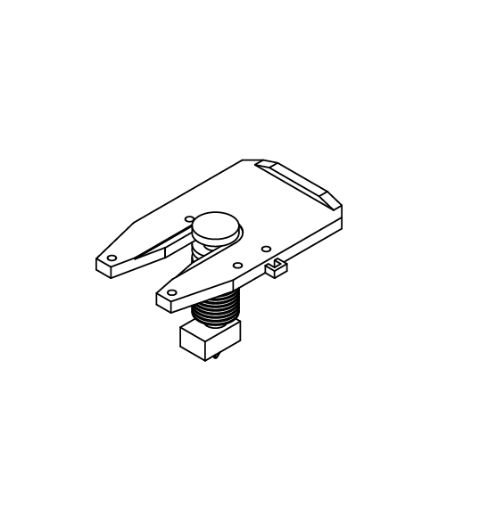
1
E
5.4
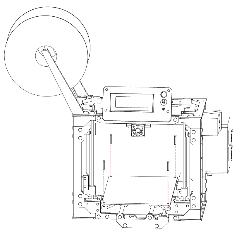
Locate the upper bed from the remaining parts kit, along with 4 compression springs, and 4 M3 X 20 screws.
Insert the screws into the upper bed, and place the
compression springs onto the screws.
Take the assembly and attach it to the lower bed.
Upper Bed Installation
X 4
M3 x 20
N/A
With the bed in place, the compression springs will allow the bed to be leveled and adjusted.
This is useful for when we set up your printer for its first print.
For now, adjust the screws so that all 4 springs appear equal.
E
5.4
2
1
E
5.5
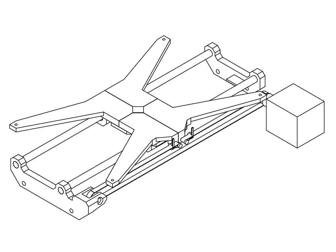
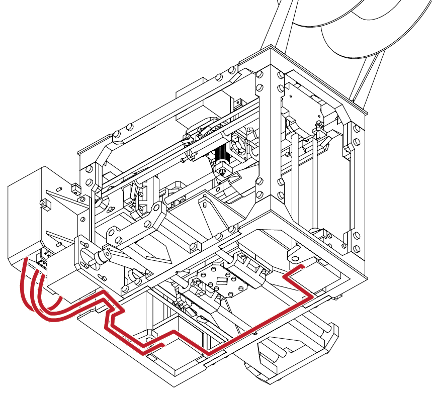
From the wiring kit, gather 3 of the wire bundles for the stepper motors.
Connect the wires to the stepper motors. Take note
that the connections are keyed and will only fit in one direction.
Route the wires similar to the diagram above.
There are several small cut-outs in the frame and areas where you may use a cable tie to secure the wires.
Wiring & Final Configuration
N/A
N/A
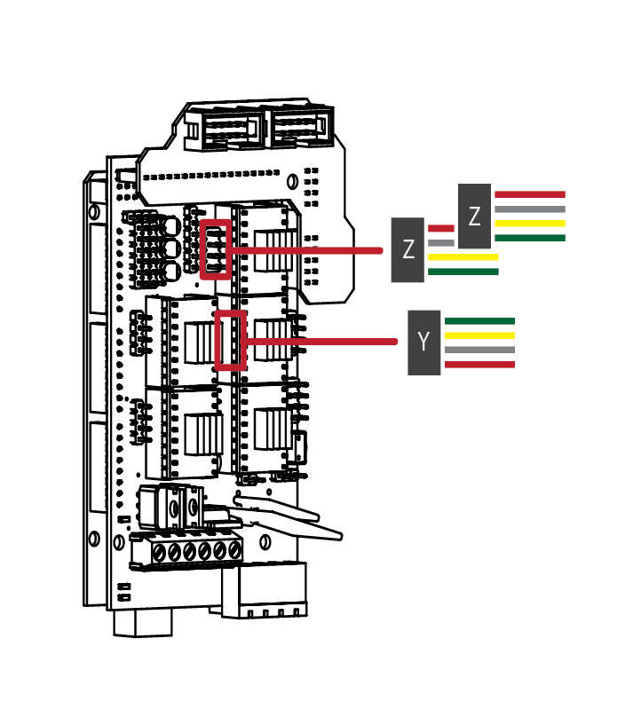
Connecting the stepper motors to the RAMPS is a very simple process.
Take one of the wire leads from the motors and attach it to the driver header pins noted above.
Note the orientation of the wire colours and how they attach to the headers.
While no damage will occur if the wires are backwards, the motor will simply run in reverse of its intended
direction.
E
5.5
2
3
E
5.5
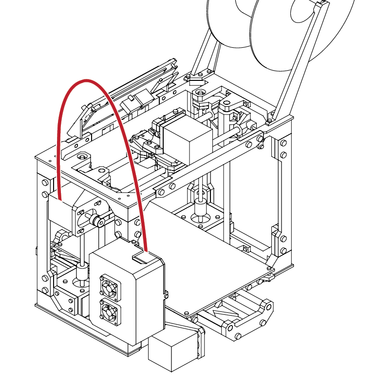
Route the stepper wires for the extruder up and over the top of the frame. Give the wire enough slack so that the extruder can freely move to each extent of the frame.

Wiring & Final Configuration
N/A
N/A
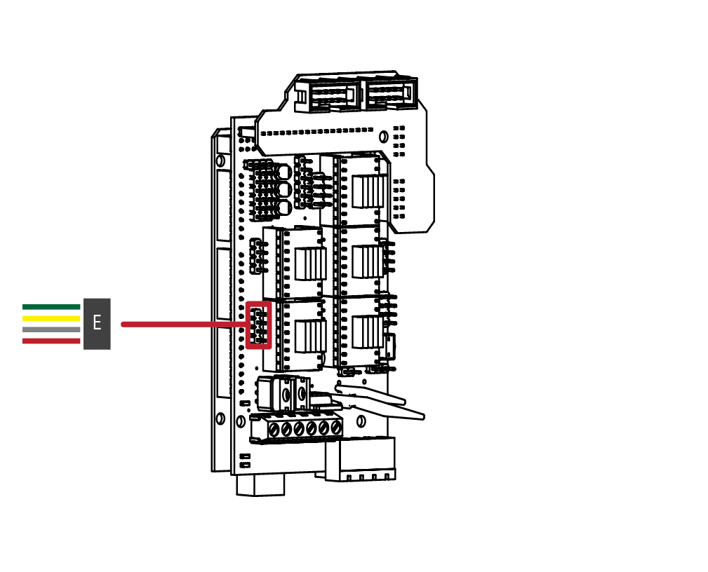
Like the previous step, attach the extruder connector to the header pins outlined above.
E
5.5
4
5
E
5.5
Route the X stepper motor wires over the side of the frame and into the electronics enclosure.
Ensure that there is enough slack in the wires so that the X axis does not bind at either extent.
Wiring & Final Configuration
N/A
N/A
Connect the X axis stepper wire to the header pin. Note the orientation of the connector.
E
5.5
6
5
E
5.5
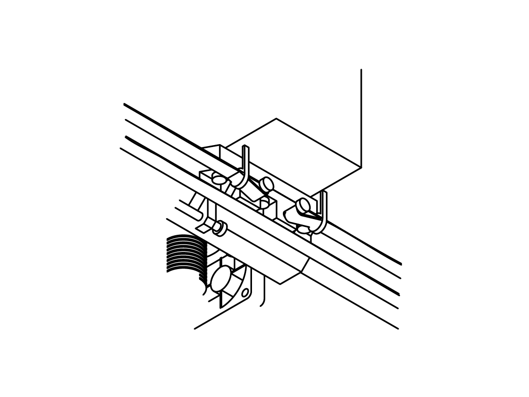
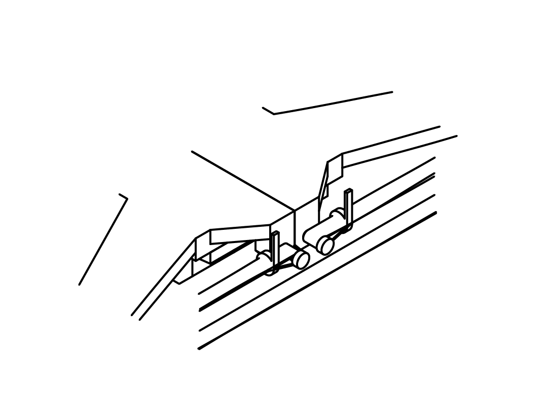
Locate the End-stops from your electronics kit.
The X axis end-stop locates the minimum starting position for the extruder assembly.
Using a hot glue gun to secure the ed stop, attach the end stop to the flang on the X axis carrier.
Align it so that trigger is in line with the long end stop screw that we attached to the extruder assembly.
Wiring & Final Configuration
N/A
N/A
Connect the X end stop according to the diagram above. The end stop is a 2 wire connector.
The end stop connector, and RAMPS board may have a 3 pin or 4 pin connector, don’t worry about this, simply ensure that both wired pins on the end stop connector are attached to pins on the RAMPS board.
E
5.5
6
7
E
5.5
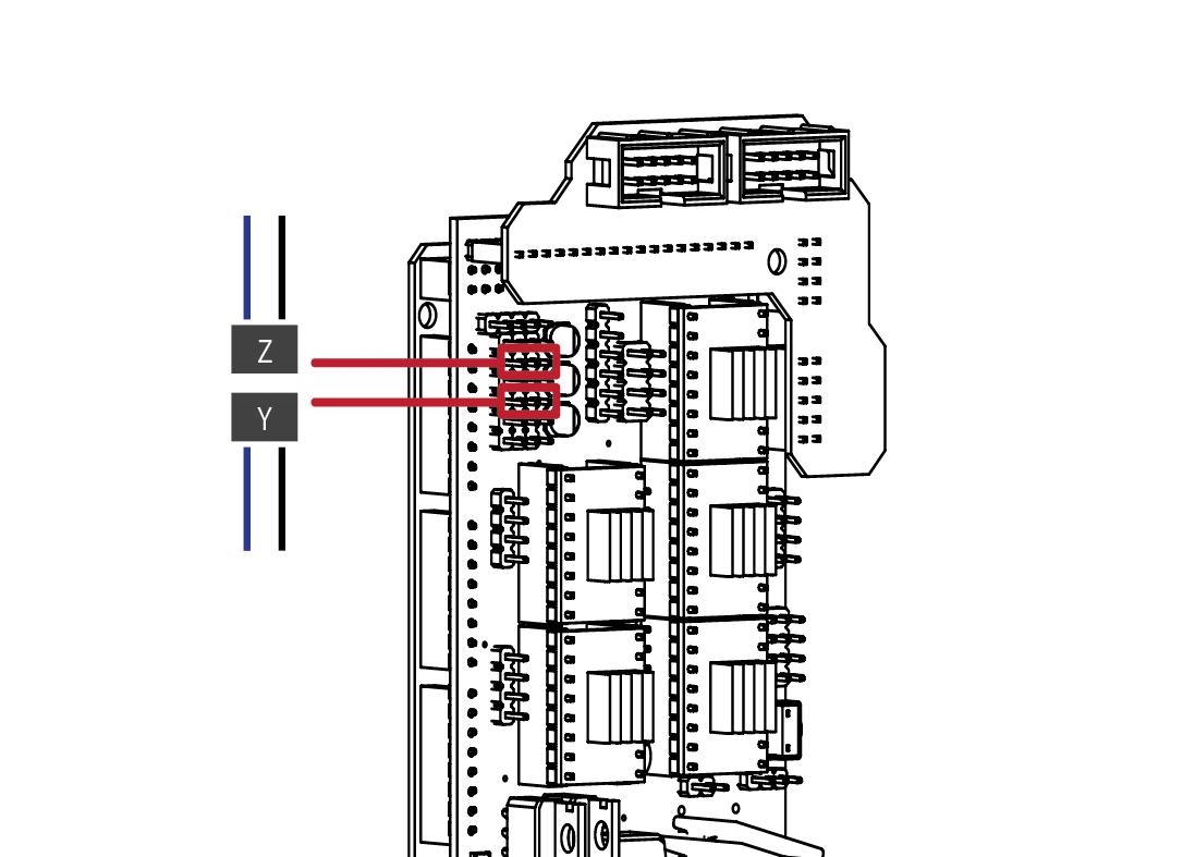
Locate the End-stops from your electronics kit.
Attach the Y axis end stop to the small shelf at the rear of the Y axis.
Attach the Z end stop to the small shelf on the side of the frame.
In both instances, ensure that the triggers are aligned with the trigger screws on both axis’. We will be fine tuning these screws later in the guide.
Wiring & Final Configuration
N/A
N/A
Connect the Y and Z end stop according to the diagram above. The end stop is a 2 wire connector.
The end stop connector, and RAMPS board may have a 3 pin or 4 pin connector, don’t worry about this, simply ensure that both wired pins on the end stop connector are attached to pins on the RAMPS board.
E
5.5
8
9
E
5.5
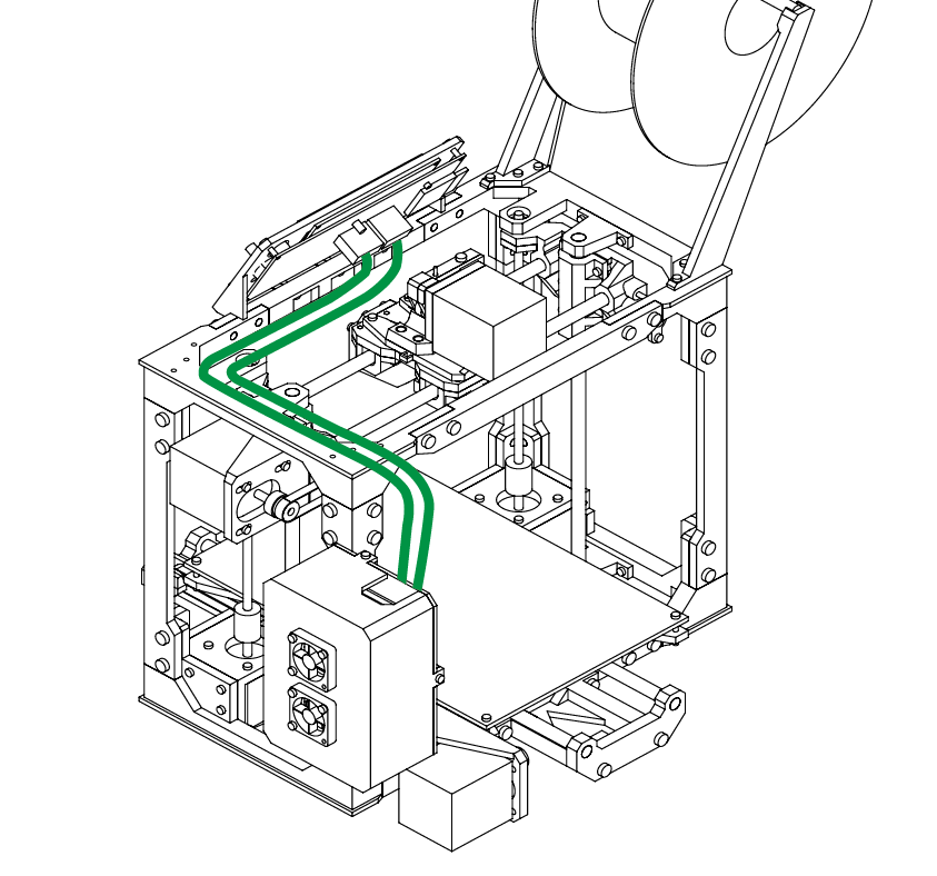
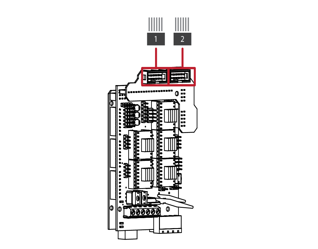
Locate the LCD ribbon cables from your electronics kit.
Attach both cables to the rear of the LCD assembly.
Use cable ties to secure the ribbon cables to the frame.
Wiring & Final Configuration
N/A
N/A
Attach the LCD ribbon cables to the top of the RAMPS electronics.
The connectors are keyed, and will only connect in a single direction.
E
5.5
10
11
E
5.5
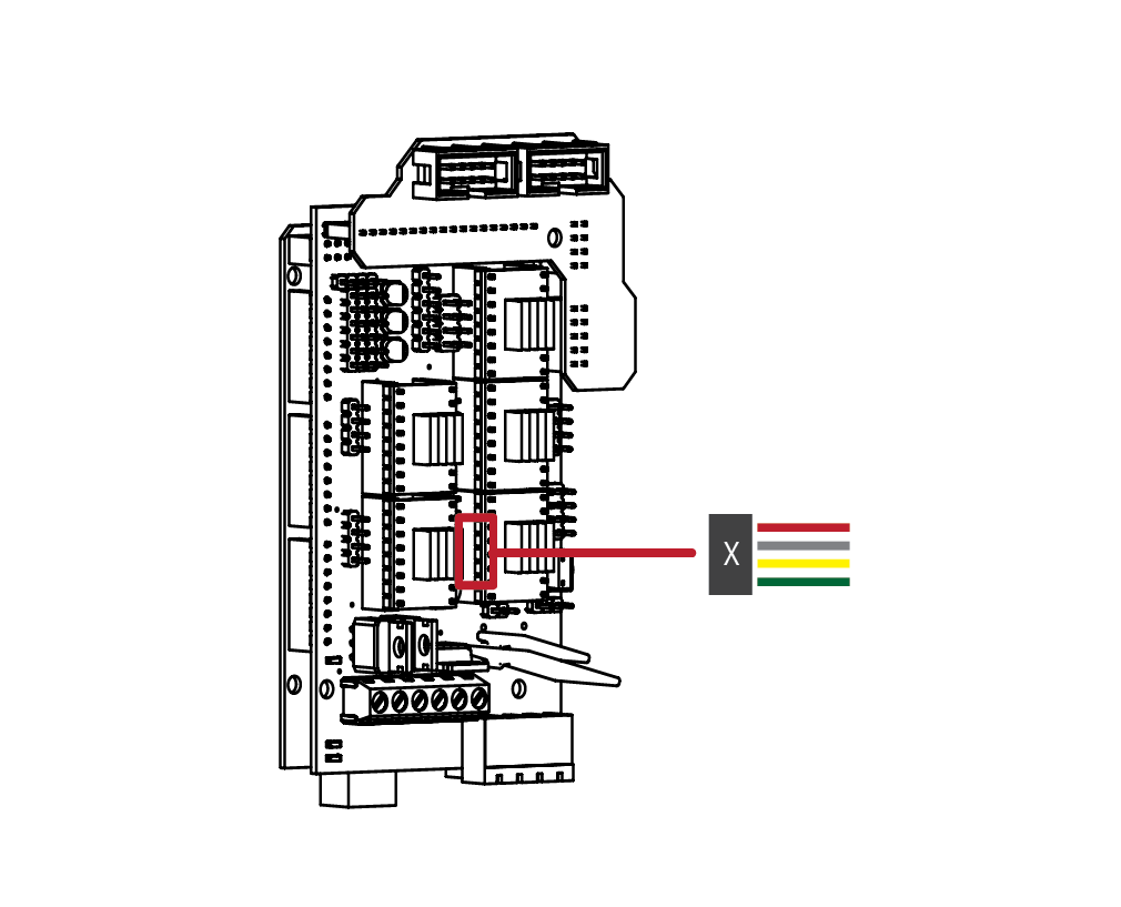
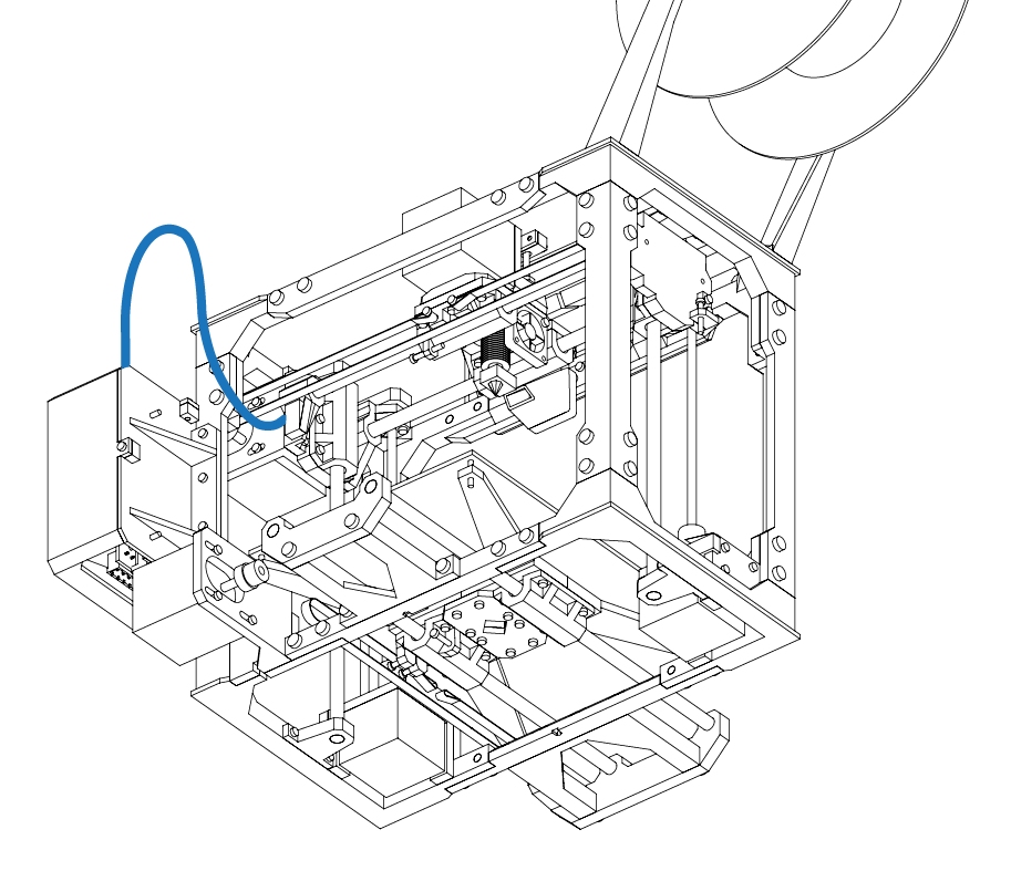
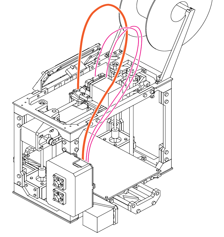
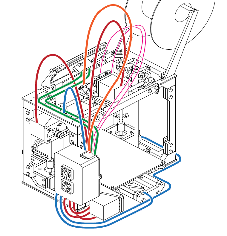
Gather the hot end heater cartridge and route it over the top of the frame and into the extruder assembly.
Route the cooling fan and hot end fan wires over the top of the frame and into the electronics enclosure.
Wiring & Final Configuration
N/A
Please refer to your hot-end’s instructions for correct assembly, however the basics are, insert the heater cartridge into the heater block and secure the cartridge with the small set screw.
Insert the thermistor into the small opening on the heater block. Use a cable tie to hold both wire sets together.
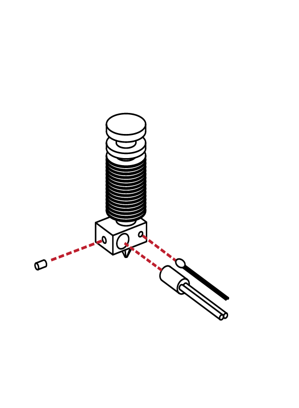
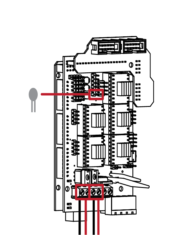
The connectors used for the hot end and cooling fan are slightly different from the other.
Attach the heater cartridge wiring to the
connectors labeled D10. Attach the Print Cooling fan to the D8 connector.
Connect the thermistor to the header pins noted above.
Hot End
Cooling Fan
E
5.5
12
13
E
5.5
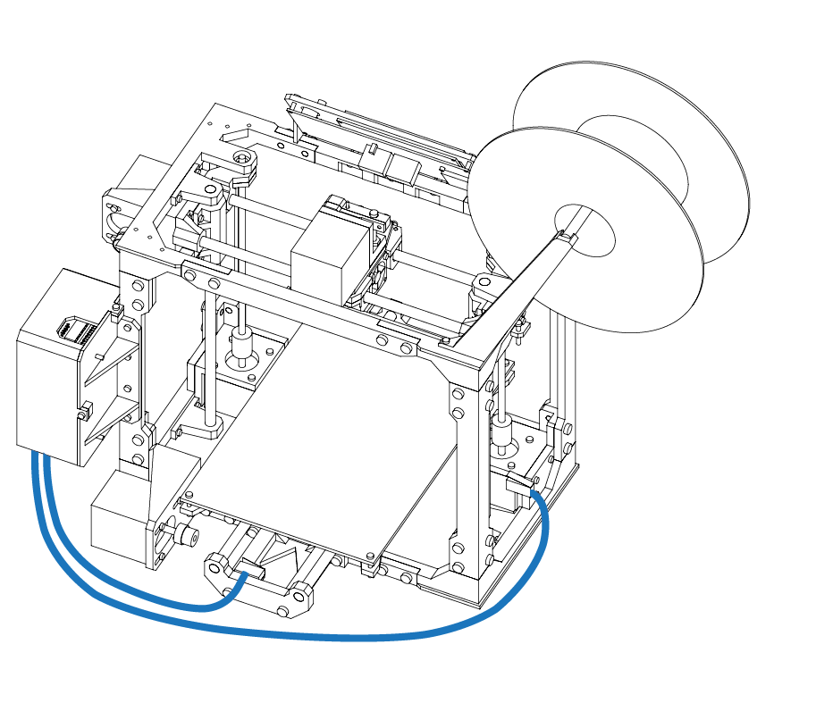
Take the final pair of wires belonging to the Hot End fan and route them over the top of the frame and into the electronics enclosure.
With the wiring mostly complete, use cable ties to neatly secure and bundle the wires.
Ensure that no wires are caught on any portion of the frame , and that all wires are long enough to reach the full extents of the printers motions.
Wiring & Final Configuration
N/A
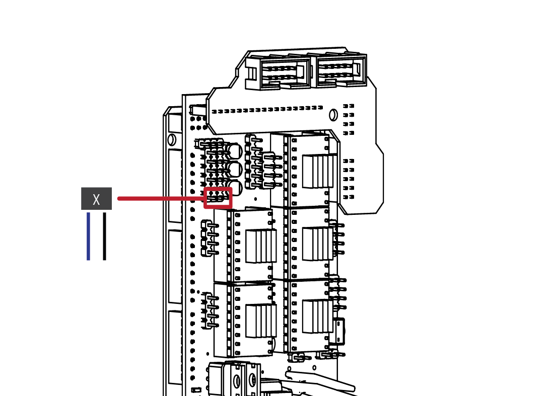
The last connection is to connect the
electronics enclosure fans to that of the main power supply.
Wire the fans in parallel to the barrel
connector, as well as the Hot end fan.
Connect a pair of wires from the barrel
connector to that of the 12V input on the RAMPS board.
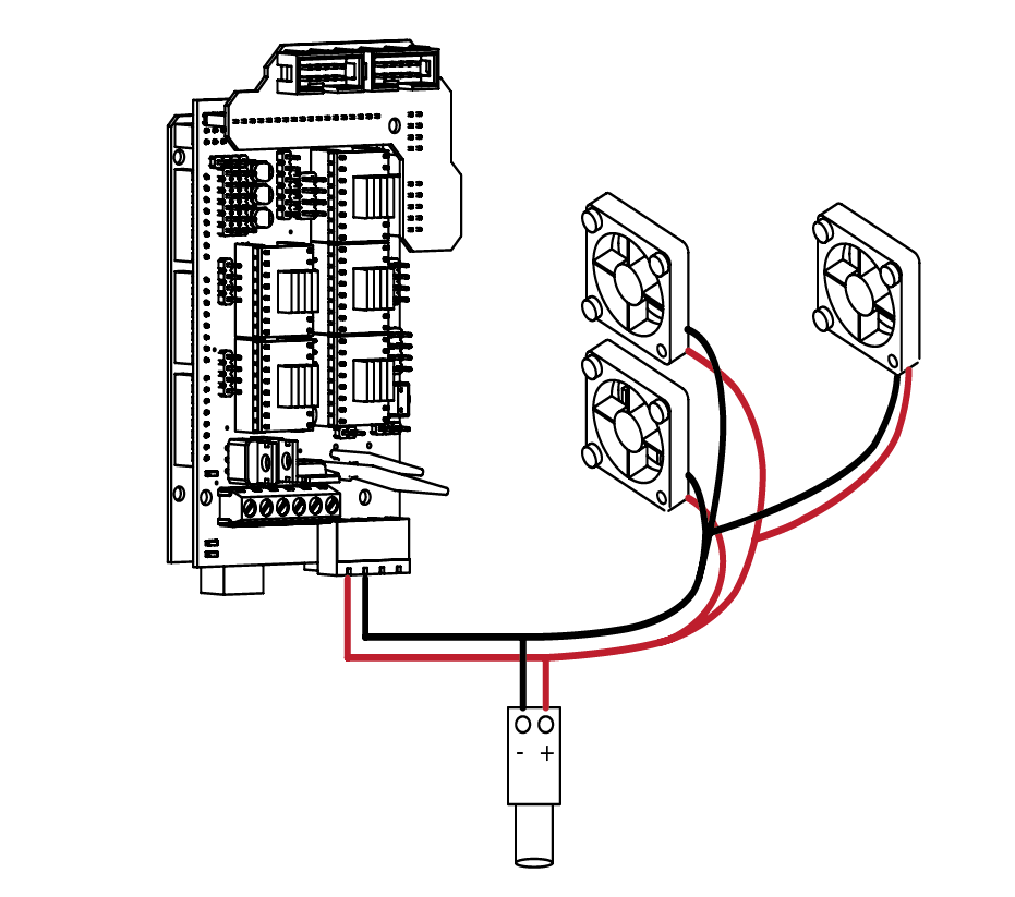
Note the polarity of the wires matches the correct polarity of the barrel connector. With the wiring complete, connect the power supply to the barrel connector and check that there is a green LED on the RAMPS board.
The electronics enclosure fans, and Hot End fan should also be operational.
Once you’ve verified that everything is
functional, re-attach the enclosure. Your
printer is now complete.
E
5.5
14
SECTION
F
6.1 Appendix 136

F
6.1
Congratulations! You’ve successfully completed the hardest portion of the build! Pat yourself on the back and marvel at the amazing piece of engineering you’ve just assembled! We’re almost ready to begin printing, but before we do, there’s a few more items we will need to cover:
Leveling Your Print Bed:
For detailed instructions on this procedure, please refer to the guides and instructions on
www.maplemakermedia.com. The following is a brief overview of the procedure.
Grab a roll of 3M Blue painters tape, and apply a layer of tape to the print bed surface. Be sure to not overlap the edges, a small gap between each strip will suffice. Unscrew the Z height screw on the side of the X axis assembly. Level the bed by adjusting the 4 screws at the corners until it appears to be roughly level.
Move the extruder to the front corner of the bed, and lower the print hed towards the bed by
rotating the Z threaded rods. We want to bring the hot end close but not touching the print bed. Grab a small scrap of paper. Slider the paper between the hot end nozzle and the bed, and lower
the extruder until the nozzle touches the paper.
You should feel some resistence when moving the paper under the nozzle. This is the ideal height for our first layer. If the bed is too high or too low, adjust the height of the bed by adjusting the bed screws until the distance is right. Repat this step for each corner of the bed. Your bed should now be roughly level.
Return to the Z height screw. The screw should not be contacting the limit switch below it. Slowly and carefully screw in the adjustment screw until it contacts the switch. Continue to adjust the screw until you hear an audible click of the switch being triggered. Congrats, your Z height is now set!
Loading the Printer’s Firmware:
For detailed instructions on this procedure, please refer to the guides and instructions on
www.maplemakermedia.com. You will need a computer, USB cable and your printer to
complete this step.
Appendix
Software Suite:
For detailed instructions on this procedure, please refer to the guides and instructions on www.maplemakermedia.com. The following is a brief overview of the procedure. Throughout the next steps, we will be using the Arduino SDK, as well as the Cura slicing engine and printer control.
The Arduino SDK can be downloaded from: http://www.arduino.cc/en/Main/Software
Cura may be downloaded from: http://wiki.ultimaker.com/Cura
A Note on Self Sourcing Builders:
For those of who wish to source their own components outside of the available kits, we want to clarify a few steps that must be taken.
You will need to cut your linear rods to length, the lengths are as follows. You will need to cut 2 of each:
X Axis: 250mm
Y Axis: 310mm
Z Axis: 250mm
Z Axis Threaded rod: 190mm
You will need to solder the wire connections to the limit switches. These are wired in the normally open (NO) configuration. Refer to the markings on the limit switch for the correct orientation. This is typically the outer pins, with the centre third pin not being used.
Additional information is available through
www.maplemakermedia.com and www.reprap.org
F
6.1
Disclaimer
While every attempt has been made to ensure the accuracy of the instructions and details contained within this guide. some parts, components or instructions may differ from what is included in your kit. For the latest instructions, guides and information, please visit www.maplemakermedia.com.
It is assumed that the user of this guide and our kit(s) have a basic understanding of how to safely
operate and use the tools required to complete this build. If you do not know how to properly
operate the required tools, refer to the original guides included with the tools for more information.
We want every experience with our kit to be a postive one. If you are unsure, or notice an error in
our documentation, please contact us using the back cover of this document, or online at
www.maplemakermedia.com.
While we strive to answer every comment and concern associated with the kit(s), the user must acknowledge and understand that we may not be able to answer every question in a timely manner. Our users are encouraged to use our online resources, as well as the www.RepRap.org resources for additional tips and tricks on building and operating their printer.
And finally, thank you, thank you for believing, and for making this a reality. We are driven by our desire to inspire others, and to expand our users capabilities and horizons. Thank you.